Brake Pedal Repair procedures
Removal
Turn ignition switch OFF and disconnect the negative (-) battery terminal.
Remove the crash pad lower panel.
(Refer to Body - "Crash Pad")
Remove the knee air bag.
(Refer to Restraint - "Knee Airbag(KAB) Module")
Remove the Steering column and shaft.
(Refer to the Steering System - "Steering Columm and Shaft")
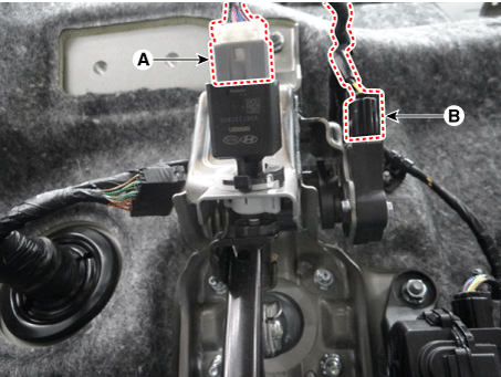
Disconnect the stop lamp switch (A) and brake pedal stroke sensor connector (B).
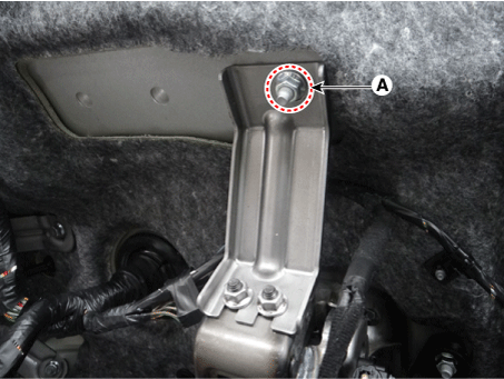
Loosen the nut (A) and then remove the bracket.
Tightening torque : 16.6 - 25 N·m
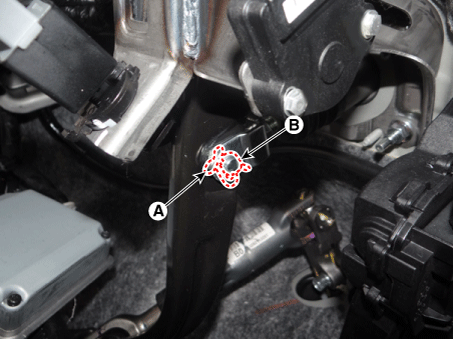
Remove the snap pin (A) and clebis pin (B).
Loosen the brake pedal nuts and then remove the brake pedal.
Tightening torque : 16.6 - 25 N·m

Installation
Installation is the reverse of removal.
Check the brake pedal operation.
Conduct the pedal traval sensor (PTS) calibration.
Diagnostic Procedure Using a Diagnostic Instrument
The following section describes how to diagnose faults using a diagnostic instrument.
Connect the diagnostic instrument to the self-diagnostic connector (16-pin) beneath the crash pad on the side of driver's seat, and then turn on the ignition to activate the diagnostic instrument.
In the GDS Vehicle Type Selection menu, select "Vehicle Type" and "Brake/VDC/AHB" System, and then opt for "OK."
Pedal Travel Sensor (PTS) Calibration
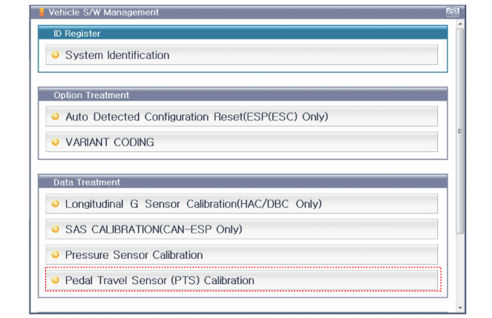
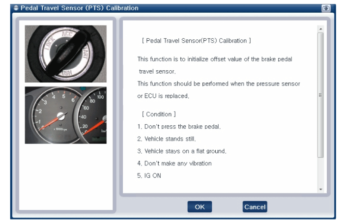
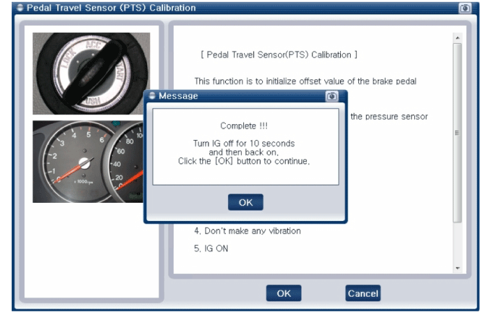
Turn ignition switch off after calibration procedure.
Confirm success or failure of calibration.