Cooling Fan Repair procedures
Removal
Shut off the High Voltage circuit.
(Refer to Hybrid Control System - “High Voltage Shutoff Procedure”)
Remove the high voltage battery front cover.
(Refer to High Voltage Battery System - "Case")
Disconnect the cooling fan connector (A).
Remove the cooling fan (B) after loosening the mounting bolt and nuts.
Cooling fan mounting nut / bolt :
7.8 - 11,8 N·m

Installation
Install the cooling fan in the reverse order of removal.
Inspection
Connect the KDS/GDS to the Data Link Connector (DLC).
Connect the oscilloscope probe to the BMS extension connectors.
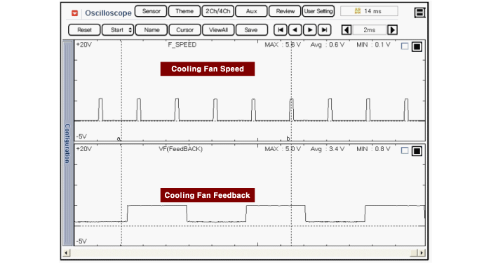
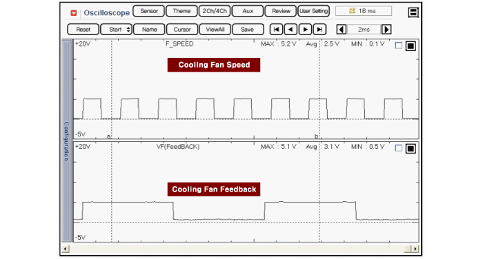
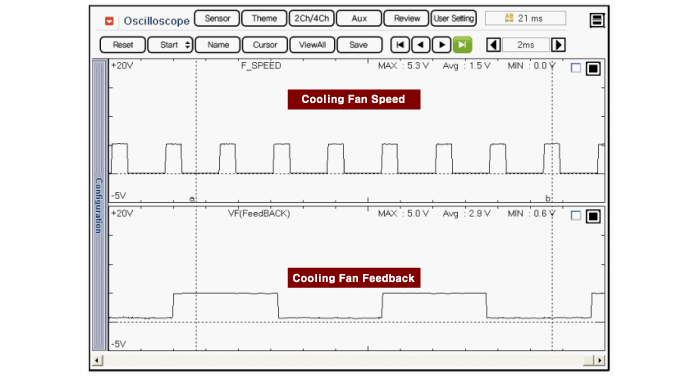
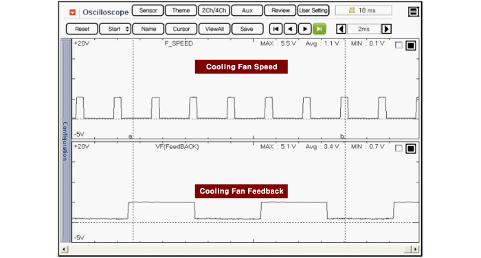
Cooling Fan Speed Waveform:
BMS Extension Connector B01-S(20)
Cooling Fan Feedback Waveform:
BMS Extension Connector B01-S(4)
Switch "ON" the ignition.
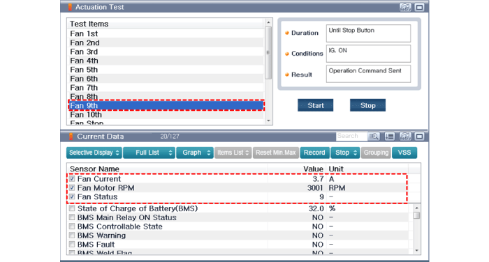
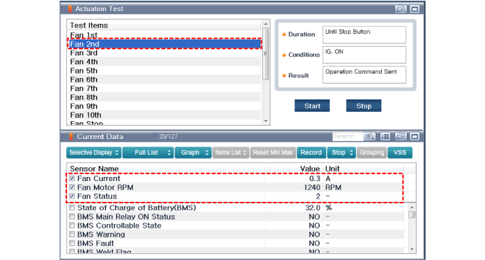
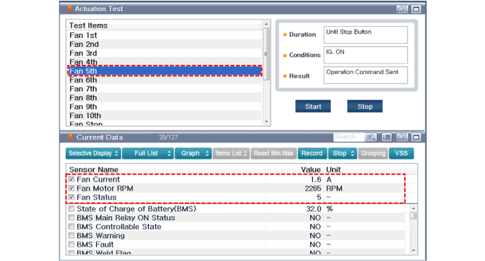
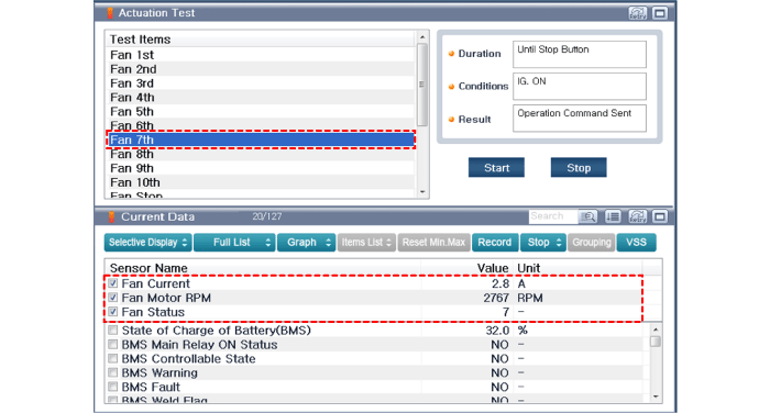
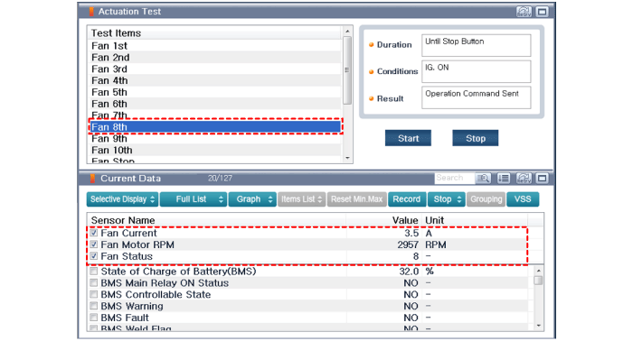
Using KDS/GDS, perform "Actuation Test" and inspect the "current and waveform in each fan operation mode".
Duty
Duty (%) Fan Speed (rpm) 10 - 20 1,000 30 1,300 40 1,600 50 1,900 60 2,200 70 2,500 80 2,800 90 3,100 95 3,850
[Cooling Fan at 1st]

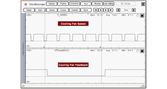
[Cooling Fan at 2nd]
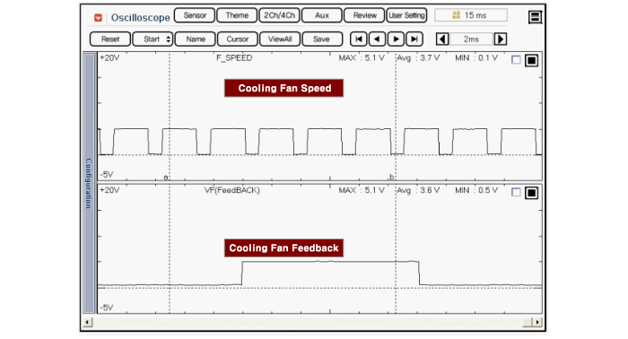
[Cooling Fan at 3rd]
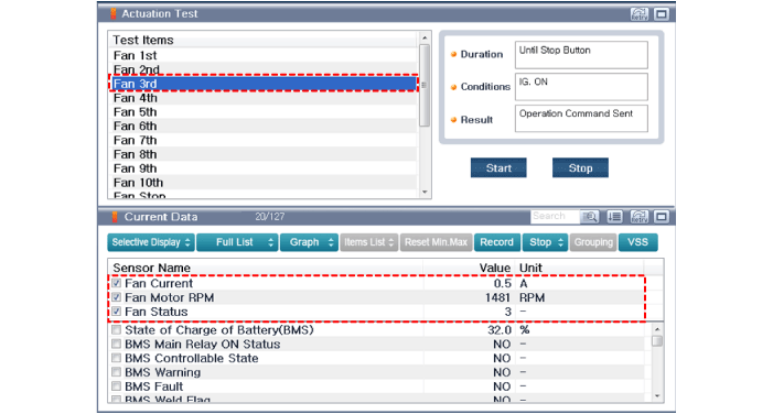

[Cooling Fan at 4th]
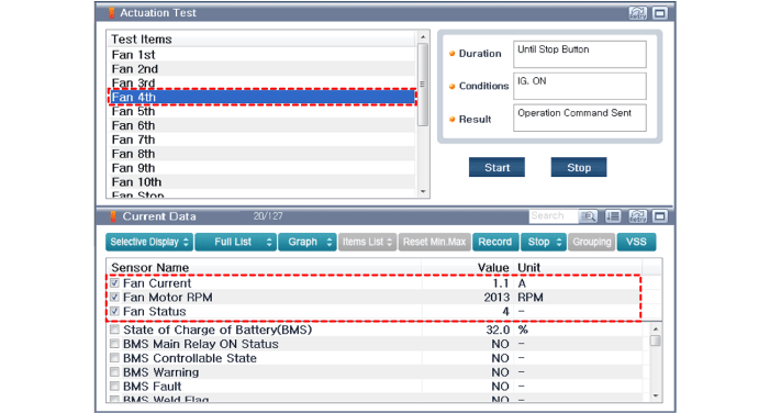
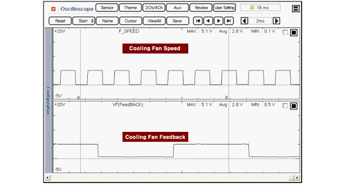
[Cooling Fan at 5th]
[Cooling Fan at 6th]


[Cooling Fan at 7th]
[Cooling Fan at 8th]
[Cooling Fan at 9th]