CVVT & Camshaft Repair procedures
Removal
Shut off the High Voltage circuit.
(Refer to General Information - "High Voltage Shutoff Procedure")
Remove the cylinder head cover.
(Refer to Cylinder Head Assembly - "Cylinder Head Cover")
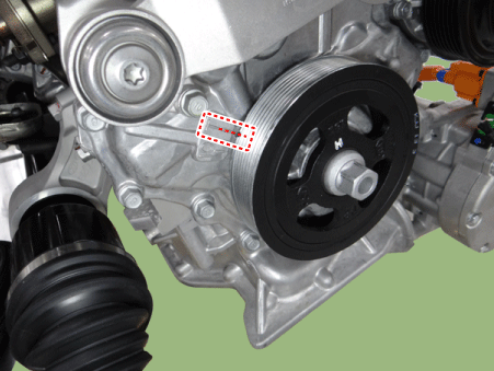
Set No.1 cylinder to TDC (Top dead center) on compression stroke.
Turn the crankshaft pulley and align its groove with the timing mark of the timing chain cover.
Mark the timing chains corresponding to the timing marks of the CVVT sprockets.

Remove the timing.
(Refer to Timing System - "Timing Chain")
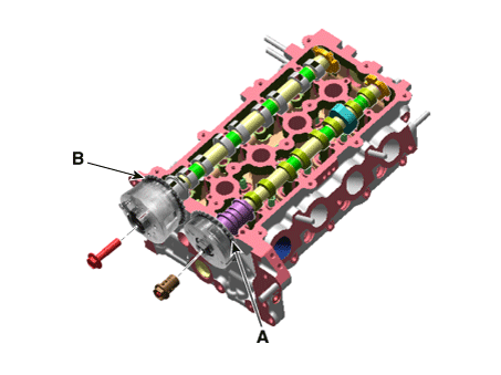
Remove the intake CVVT assembly (A) and exhaust CVVT assembly (B).
Remove the camshaft.
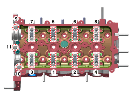
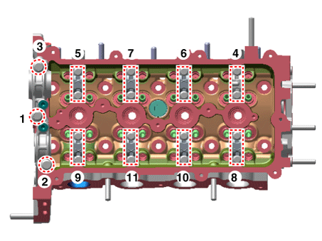
Remove the camshaft front bearing cap and camshaft bearing cap in the sequence shown.
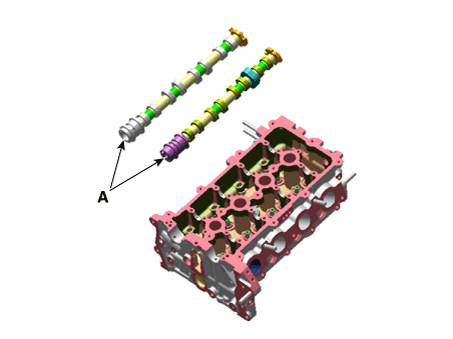
Remove the camshafts (A).
Inspection
Camshaft
Inspect the cam lobes.
Using a micrometer, measure the cam lobe height.
If the cam lobe height is less than specification, replace the camshaft.
Cam height : Intake: 36..42 mm (1.4339 in.) Exhaust: 36.15 mm (1.4232 in.)

Check the surface of the camshaft journal for wear.
If the journal is worn excessively, replace the camshaft.
Inspect the camshaft journal clearance.
Clean the bearing caps and camshaft journals.
Place the camshafts on the cylinder head.
Lay a strip of plastigage across each of the camshaft journal.
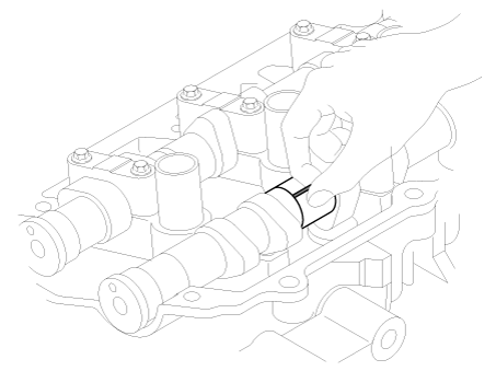
Install the camshaft front bearing cap and camshaft bearing cap in the sequence shown.
Tightening torque
Step 1
M6 bolts :
5.9 N.m (0.6 kgf.m, 4.3 lb-ft)
M8 bolts :
9.8 N.m (1.0 kgf.m, 7.2 lb-ft)
Step
2M6 bolts :
11.8 - 13.7 N.m (1.2 - 1.4 kgf.m, 8.7 - 10.1 lb-ft)
M8 bolts :
18.6 - 22.6 N.m (1.9 - 2.3 kgf.m, 13.7 - 16.6 lb-ft)
Remove the bearing caps.
Measure the plastigage at its widest point.
If the oil clearance is greater than specification, replace the camshaft. If necessary, replace the bearing caps and cylinder head as a set.
Camshaft bearing oil clearance
Intake
No. 1 :
0.032 - 0.062 mm (0.0013 - 0.0024 in.)
No. 2,3,4,5 :
0.027 - 0.057 mm (0.0011 - 0.0022 in.)
Exhaust
No. 1 :
0.027 - 0.057 mm (0.0011 - 0.0022 in.)
No. 2,3,4,5 :
0.027 - 0.057 mm (0.0011 - 0.0022 in.)

Inspect the camshaft end play.
Install the camshaft bearing caps.
Using a dial indicator, measure the end play while moving the camshaft back and forth.
If the end play is greater than specification, replace the camshaft.
If necessary, replace the bearing caps and cylinder head as a set.
Camshaft end play : Standard : 0.10 - 0.20mm (0.0039 - 0.0079 in.)

Remove the camshafts.
Continuous variable valve timing (CVVT) Assembly
Clamp the camshaft using a vise. Be careful not to damage the cam lobes and journals in the vise.
Rotate the CVVT clockwise and counterclockwise to make sure that it is locked. It must not rotate.
Intake CVVT : Seal one of the two advance holes in the camshaft journal with tape.
Exhaust CVVT : Seal one of the two retard holes in the camshaft journal with tape.

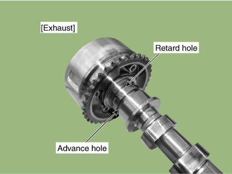
Intake CVVT : Apply approx. 150 kPa (1.5 kgf/cm², 21 psi) of compressed air into the unsealed advance hole to release the lock.
Exhaust CVVT : Apply approx. 150 kPa (1.5 kgf/cm², 21 psi) of compressed air into the unsealed retard hole to release the lock.
Intake CVVT : With compressed air applied, rotate the CVVT in the advance direction (counterclockwise) within its phasing range and check that the CVVT turns smoothly.
Exhaust CVVT : With compressed air applied, rotate the CVVT in the retard direction (clockwise) and check that the CVVT turns smoothly.
CVVT phasing range :
Intake : .35°±1°" (from the most retarded position to the most advanced position)
Exhaust : 20°±1°" (from the most advanced position to the most retarded position)
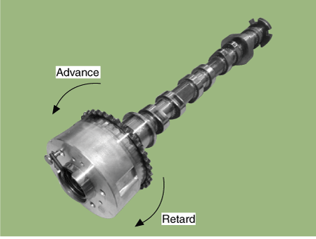
Intake CVVT : Rotate the CVVT into the most retarded position (clockwise) and then check that the CVVT is locked.
Exhaust CVVT : Rotate the CVVT into the most advanced position (counterclockwise) and then check that the CVVT is locked.
Installation
Install the camshaft.
Install the camshafts (A).
Install the camshaft front bearing cap and camshaft bearing cap in the sequence shown.
Tightening torque
Step
1M6 bolts :
5.9 N.m (0.6 kgf.m, 4.3 lb-ft)
M8 bolts :
9.8 N.m (1.0 kgf.m, 7.2 lb-ft)
Step
2M6 bolts :
11.8 - 13.7 N.m (1.2 - 1.4 kgf.m, 8.7 - 10.1 lb-ft)
M8 bolts :
18.6 - 22.6 N.m (1.9 - 2.3 kgf.m, 13.7 - 16.6 lb-ft)
Install the intake CVVT assembly (A) and exhaust CVVT assembly (B).
Tightening torque
Intake CVVT OCV bolt :
[47.1 - 52.0 N.m (4.8 - 5.3 kgf.m, 34.7 - 38.3 lb-ft)] + [25 - 31°]
Exhaust CVVT bolt :
63.7 - 73.5 N.m (6.5 - 7.5 kgf.m, 47.0 - 54.2 lb-ft)
Install in the reverse order of removal.