Cylinder Head Repair procedures
Removal
Engine removal is not required for this procedure.
Shut off the High Voltage circuit.
(Refer to Engine Mechanical System - "High Voltage Shutoff Procedure")
Remove the air cleaner assembly.
(Refer to Intake and Exhaust System - "Air Cleaner")
Remove the engine room under cover.
(Refer to Engine and Transaxle Assembly - "Engine Room Under Cover")
Drain the engine coolant.
(Refer to Cooling System - "Coolant")
Drain the inverter coolant.
(Refer to Hybrid Motor System - "Coolant")
Disconnect the radiator upper hose (A).

Disconnect the radiator lower hose (A).

Remove the hybrid power control unit (HPCU) and tray.
(Refer to Hybrid Control System - "Hybrid Power Control Unit (HPCU)")
Disconnect the reservoir tank coolant hose (A).

Disconnect the hybrid starter generator (HSG) coolant hose (A).
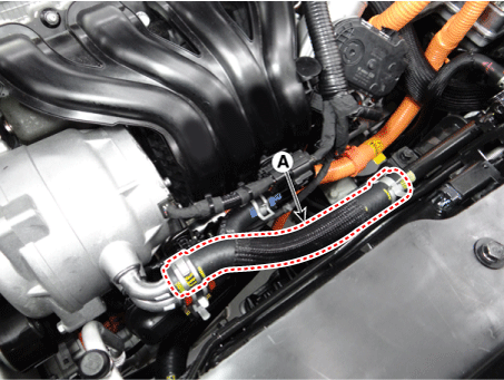
Disconnect the electric water pump (EWP) coolant hose (A).

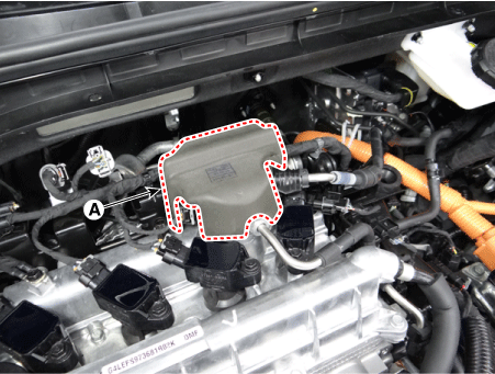
Remove the high pressure fuel pump foam (A).
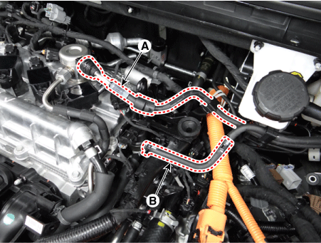
Disconnect the fuel hose (A) and purge control solenoid valve (PCSV) hose (B).
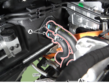
Disconnect the heater hose (A).
Remove the front muffler.
(Refer to Intake and Exhaust System - "Muffler")
Remove the water temperature control assembly and heater pipe.
(Refer to Cooling System - "Water Temperature Control Assembly")
Remove the intake manifold.
(Refer to Intake and Exhaust System - "Intake Manifold")
Remove the hybrid starter generator (HSG).
(Refer to Hybrid Motor System - "Hybrid Starter Generator (HSG)")
Remove the electric EGR control valve.
(Refer to Engine Control/Fuel System - "Electric EGR Control Valve")
Remove the spark plugs.
(Refer to Engine Electrical System - "Spark Plug")
Remove the cylinder head cover.
(Refer to Cylinder Head Assembly - "Cylinder Head Cover")
Remove the exhaust manifold.
(Refer to Intake and Exhaust System - "Exhaust Manifold")
Remove the timing chain.
(Refer to Timing System - "Timing Chain")
Remove the CVVT & camshaft.
Remove the camshaft front bearing cap and camshaft bearing cap in the sequence shown.
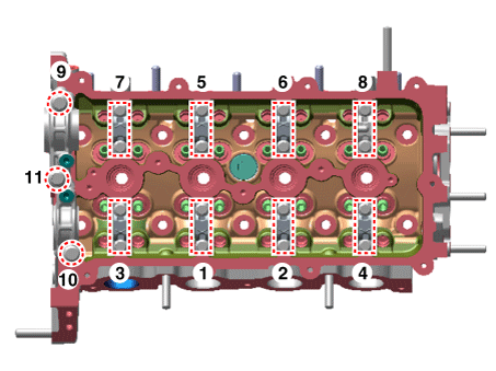
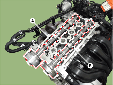
Remove the exhaust CVVT & camshafts (A) and intake camshaft (B).
Remove the hydraulic lash adjuster (HLA) (A) and the swing arm (B).

Remove the cylinder head.
Using triple square wrench, uniformly loosen and remove the 10 cylinder head bolts, in several passes, in the sequence shown. Remove the 8 cylinder head bolts and plate washers.
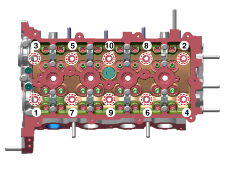
Lift the cylinder head (A) from the dowels on the cylinder block and place the cylinder head on wooden blocks on a bench.
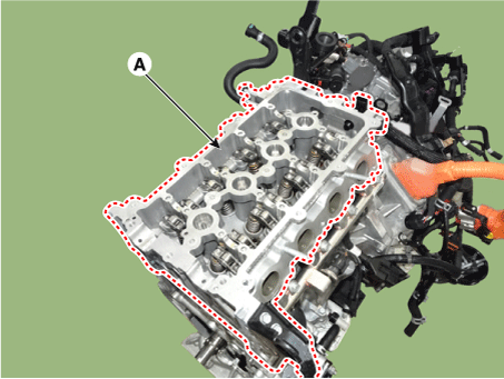
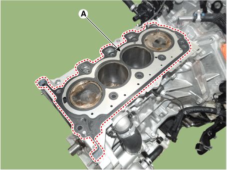
Remove the cylinder head gasket (A).
Disassembly
Remove the valves.
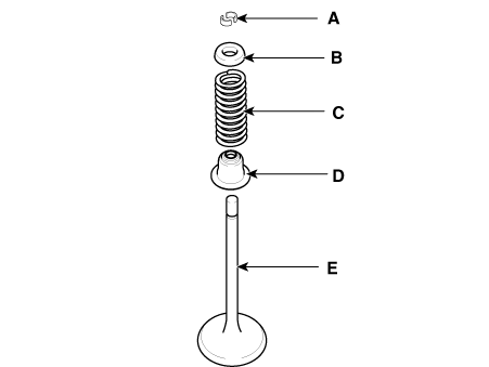
Using the SST (09222-3K000, 09222-3K100), compress the valve spring and remove the retainer lock (A).
Remove the spring retainer (B).
Remove the valve spring (C).
Remove the valve (D).
Using needle-nose pliers, remove the valve stem seal (E).
Inspection
Cylinder Head
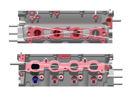
Inspect for flatness.
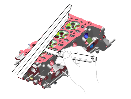
Using a precision straight edge and feeler gauge, measure the contacting surface of the cylinder block and check the manifolds for warpage.
Flatness of cylinder head gasket surface :
Less than 0.05 mm (0.0020 in.) for total area
Less than 0.02 mm (0.0008 in.) for a section of 100 mm (3.9370 in.) X 100 mm (3.9370 in.)
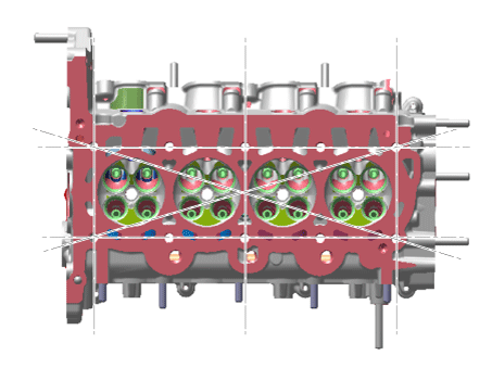
Flatness of manifold mounting surface : Less than 0.10 mm (0.0039 in.)
Inspect for cracks.
Check the combustion chamber, intake ports, exhaust ports and cylinder block surface for cracks. If cracked, replace the cylinder head.
Valve And Valve Spring
Inspect valve stems and valve guides.
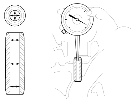
Using a caliper gauge, measure the inside diameter of the valve guide.
Valve guide inner diameter :
Intake : 5.500 - 5.512 mm (0.21654 - 0.21701 in.)
Exhaust : 5.500 - 5.512 mm (0.21654 - 0.21701 in.)
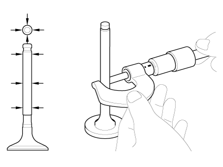
Using a micrometer, measure the diameter of the valve stem.
Valve stem outer diameter :
Intake : 5.465 - 5.480 mm (0.21516 - 0.21575 in.)
Exhaust : 5.458 - 5.470 mm (0.21488 - 0.21535 in.)
Subtract the valve stem diameter measurement from the valve guide inside diameter measurement.
If the clearance is greater than specification, replace the valve or the cylinder head.
Valve stem-to-guide clearance :
[Standard]
Intake : 0.020 - 0.047 mm (0.00079 - 0.00185 in.)
Exhaust : 0.030 - 0.044 mm (0.00118 - 0.00252 in.)
Inspect the valves.
Check that the valve is ground to the correct valve face angle.
Check the surface of the valve for wear.
If the valve face is worn, replace the valve.
Check the valve head margin thickness.
If the margin thickness is less than specification, replace the valve.
Margin
[Standard]
Intake : 1.35 - 1.65 mm (0.0531 - 0.0650 in.)
Exhaust : 1.60 - 1.90 mm (0.0630 - 0.0748 in.)

Check the valve length.
Valve length : Intake: 100.94 mm (3.9740 in.) Exhaust: 101.09 mm (3.9740 in.)
Check the surface of the valve stem tip for wear.
If the valve stem tip is worn, replace the valve.
Inspect the valve seats and the valve guides.
Check the valve seat for evidence of overheating and improper contact with the valve face.
If the valve seat is worn, replace the cylinder head.
Check the valve guide for wear. If the valve guide is worn, replace the cylinder head.
Inspect the valve springs
Using a steel square, measure the out-of-square of valve spring.
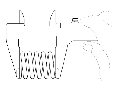
Using a vernier calipers, measure the free length of valve spring.
If the free length is not as specified, replace the valve spring.
Valve spring :
[Standard]
Free height:
50.27 mm (1.9791 in.)
Load :
16.4 ± 0.8 kgf·m / 35.5 mm (36.16 ± 1.76 lb·f / 1.3976 in.) 26.0 ± 0.9 kgf·m / 22.7 mm (57.32 ± 1.98 lb·f / 0.8937 in.)
Out-of-square :
Less than 1.5°
HLA (Hydraulic Lash Adjuster)
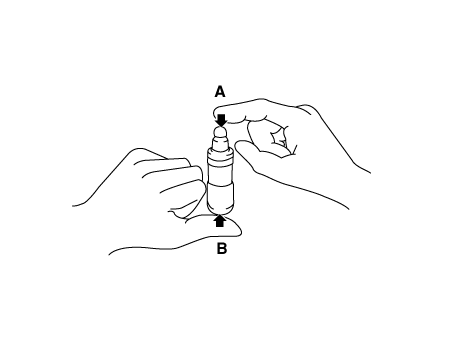
With the HLA filled with engine oil, hold A and press B by hand.
If B moves, replace the HLA.
| Problem | Possible cause | Action |
| 1. Temporary noise when starting a cold engine | Normal | This noise will disappear after the oil in the engine reaches the normal pressure. |
| 2. Continuous noise when starting the engine after being parked for more than 48 hours | Oil leakage of the high pressure chamber on the HLA, allowing air to get in | Noise will disappear within 15 minutes when engine runs at 2000-3000 rpm. If it doesn’t disappear, refer to step 7 below. |
| 3. Continuous noise when the engine is first started after rebuilding cylinder head | Insufficient oil in cylinder head oil gallery | |
| 4. Continuous noise when the engine is started after excessively cranking the engine by the starter motor or band |
|
|
| 5. Continuous noise when the engine is running after changing the HLA | ||
| 6. Continuous noise during idle after high engine speed | Engine oil level too high or too low |
|
| Excessive amount of air in the oil at high engine speed | Check oil supply system. | |
| Deteriorated oil | Check oil quality. If deteriorated, replace with specified type. |
|
| 7. Noise continues for more than 15 minutes | Low oil pressure | Check oil pressure and oil supply system of each part of engine. |
| Faulty HLA | Remove the cylinder head cover and press HLA down by hand. If it moves, replace the HLA. |
Reassembly
Install the valves.
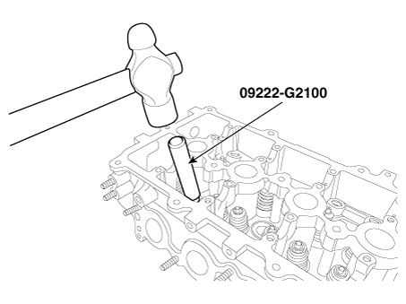
Using the SST (09222-2G100), push in a new stem seal.
Install the valve, valve spring and spring retainer.
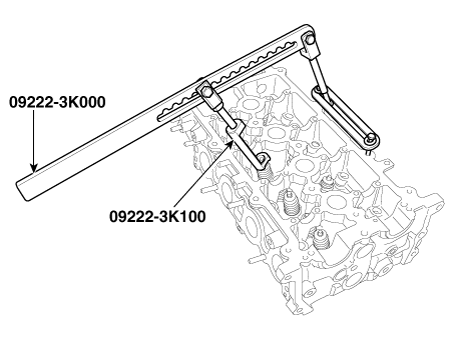
Using the SST (09222-3K000, 09222-3K100), compress the spring and install the retainer locks.
Before releasing the valve spring compressor, ensure that the retainer locks are correctly in place after pushing down and releasing the compressor handle 2 - 3 times.
Installation
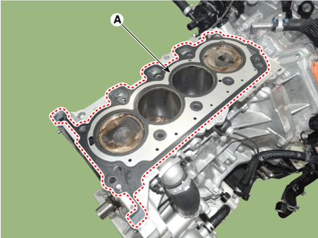
Install the cylinder head gasket on the cylinder block.
Remove hardening sealant, oil, dust, moisture and harmful foreign materials from the cylinder block and the cylinder head.
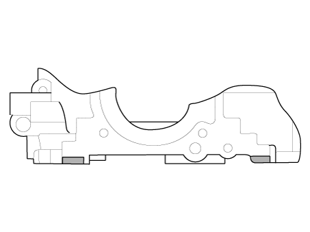
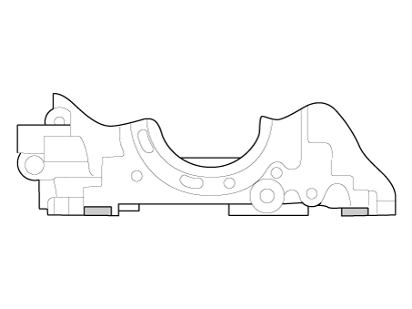
Apply liquid gasket on the edge of the cylinder block.
Sealant: Threebond 1217H or equivalent
Install the cylinder head gasket (A) with the dowel pins of the cylinder block.
Apply liquid gasket on the edge of the cylinder head gasket.
Sealant: Threebond 1217H or equivalent
Install the cylinder head assembly.
Carefully place the cylinder head (A) so as not to damage the gasket.
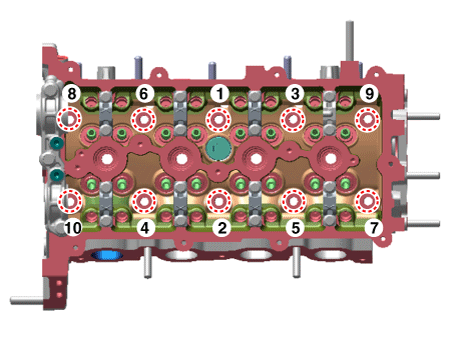
Tighten the cylinder head bolts and plate washers, in several passes, in the sequence shown.
Tightening torque :
[12.7 - 16.7 N.m (1.3 - 1.7 kgf.m, 9.4 - 12.3 lb-ft)] + [120 - 125°] + [120 - 125°]
Install the hydraulic lash adjuster (HLA) (A) and the swing arm (B).
When installing HLA, it should be held upright so that engine oil in HLA may not spill and assured that dust does not adhere to HLA.
HLA should be inserted carefully to the cylinder head not to spill engine oil.
Install the remaining parts in the reverse order of removal.
Add all the necessary fluids and check for leaks.
Connect KDS/GDS. Check for codes, note, and clear. Recheck.