Front Strut Assembly Repair procedures
Removal
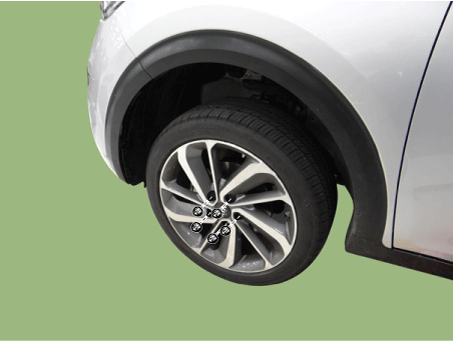
Remove the wheel and tire.
Tightening torque: 107.9 - 128 N·m
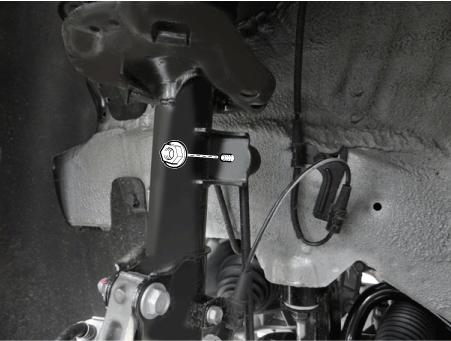
Remove the stabilizer link nut.
Tightening torque: 98.0 - 118 N·m
Remove the wheel speed sensor bracket bolt (A).
Tightening torque: 8.8 - 13,7 N·m

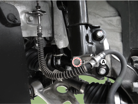
Remove the caliper hose bracket bolt (A).
Tightening torque: 8.8 - 13,7 N·m
Loosen the front strut lower bolts.
Tightening torque: 156.9 - 176 N·m

Remove the cowl top cover.
(Refer to Body - "Cowl Top Cover")
Loosen the front strut upper nuts and then remove the strut assembly.
Tightening torque: 53.9 - 74 N·m

Disassembly
Compress and extend the piston rod and check that there is no abnormal resistance or unusual sound during operation.
Remove the insulator cap (A).
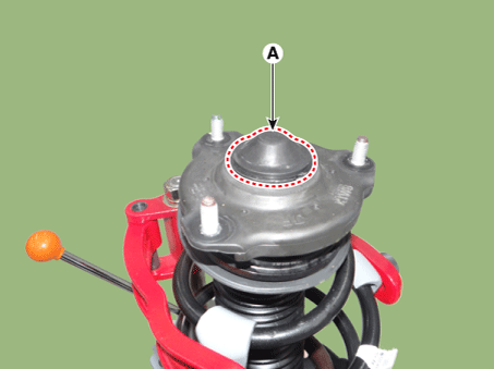
Loosen the insulator nut (A) and then remove the insulator.
Tightening torque: 78.5 - 88 N·m
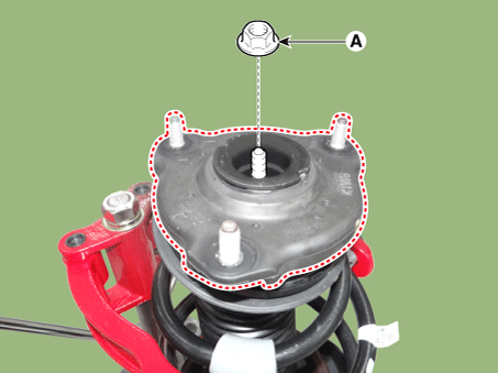
Remove the strut bearing, spring upper pad and ruber.
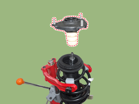
Remove the spring (A) and dust cover (B).

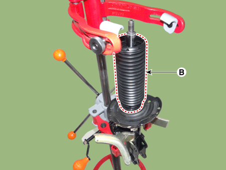
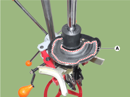
Remove the spring lower pad (A).
Inspection
Check the strut insulator for wear or damage.
Check rubber parts for damage or deterioration.
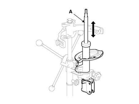
Compress and extend the piston rod (A) and check that there is no abnormal resistance or unusual sound during operation.
Disposal
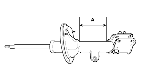
Fully extend the piston rod.
Drill a hole on the A section to remove gas from the cylinder.
Reassembly
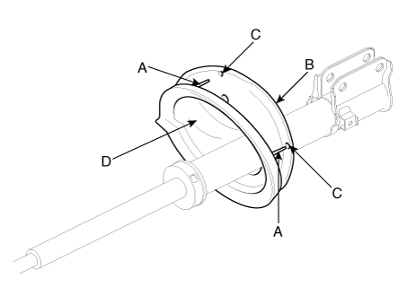
Install the spring lower pad (D) so that the protrusions (A) fits in the holes (C) in the spring lower seat (B).
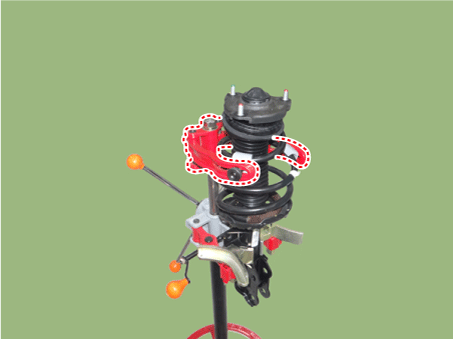
Compress coil spring using special tool (09546-26000). Install compressed coil spring into shock absorber.
After fully extending the piston rod, install the spring upper seat and insulator assembly.
After seating the upper and lower ends of the coil spring (A) in the upper and lower spring seat grooves (B) correctly, tighten new self-locking nut temporarily.
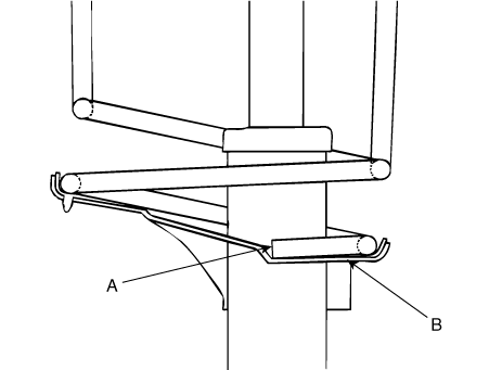
Remove the special tool (09546-26000).
Tighten the self-locking nut to the specified torque.
Tightening torque : 58.8 - 69 N·m