Sub Frame Repair procedures
Removal
Disconnect the battery negative cable.
Remove the universal bolt (A).
Tightening torque : 32.4 - 37 N·m

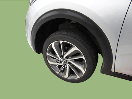
Remove the wheel and tire.
Tightening torque: 107.9 - 128 N·m
Remove the under cover.
(Refer to Engine Mechanical System - "Engine Room Under Cover")
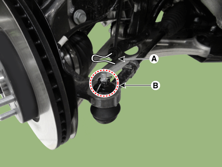
Remove the tie rod end pin (A) and nub (B).
Tightening torque: 78.4 - 98 N·m
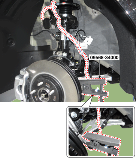
Remove the knuckle by using the SST (09568-34000).
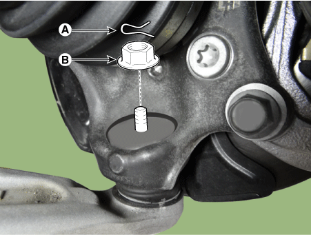
Remove the lower arm pin (A) and nut (B).
Tightening torque: 78.4 - 98 N·m
Remove the stabilizer link nut.
Tightening torque: 98.0 - 118 N·m
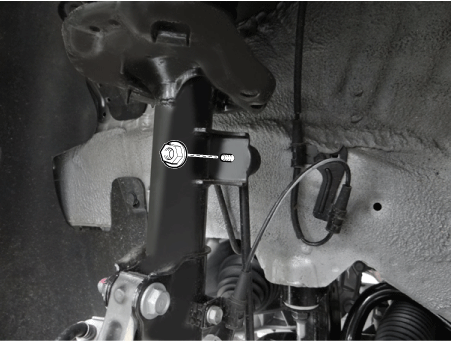
Loosen the nuts and then remove the heat protector.

Remove the hanger (A).

Remove the roll rod bracket.
(Refer to Engine Mechanical System - "Engine Mounting")
Loosen the bolts (A) and (B) and then remove the coolant pipe.
Tightening torque: 6.8 - 10,7 N·m
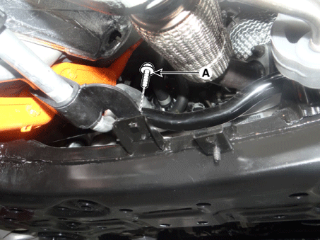
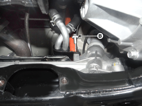
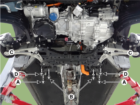
Loosen the bolts (A,B) and nuts (C,D) and then remove the sub frame (D).
Tightening torque:
Bolts :
(A) 44.1 - 54 N·m
(B) 156.9 - 176 N·m
Nuts :
(C) 156.9 - 176 N·m
(D) 44.1 - 54 N·m
Loosen the bolts and then remove the gearbox heat protector.
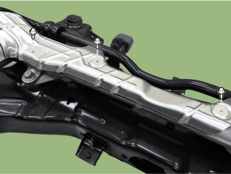
Loosen the bolts and then remove the front stabilizer bar.
Tightening torque: 44.1 - 54 N·m

Loosen the bolts and then remove the gear box.
Tightening torque:
88.3 - 107.9 - 128 N·m

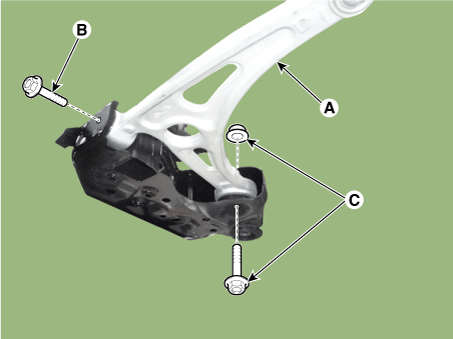
Loosen the bolts (B,C) and then remove the lower arm (A) from the sub frame.
Tightening torque:
(B) 117.7 - 137 N·m
(C) 156.9 - 176 N·m
Install in the reverse order of removal.
Check the wheel alignment.
(Refer to Suspension System - "Alignment")