Power Relay Assembly (PRA) Repair procedures
Removal
Shut off the high voltage circuit.
(Refer to Hybrid Control System - “High Voltage Shutoff Procedure”)
Remove the rear seat cushion.
(Refer to Body - "Rear Seat Assembly")
Remove the rear door scuff trim.
(Refer to Body - "Door Scuff Trim")
Remove the cooling duct.
(Refer to High Voltage Battery Cooling System - "Cooling Duct")
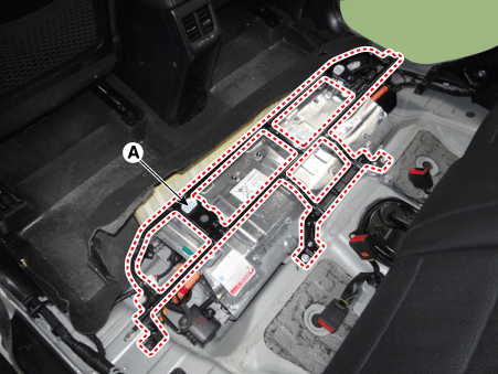
Remove the upper frame (A) after loosening the mounting bolts and nuts.
High voltage battery system assembly upper frame mounting bolt :
19.6 - 29 N·m
High voltage battery system assembly upper frame mounting nut (M8) :
19.6 - 29 N·m
High voltage battery system assembly upper frame mounting nut (M6) :
7.8 - 11,8 N·m
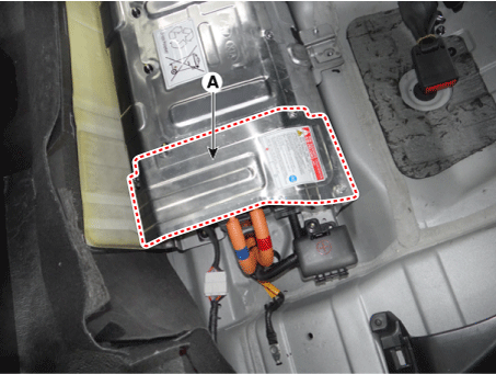
Remove the high voltage battery rear cover (A) after loosening the mounting bolts and nuts.
High voltage battery rear cover mounting bolt / nut :
7.8 - 11,8 N·m
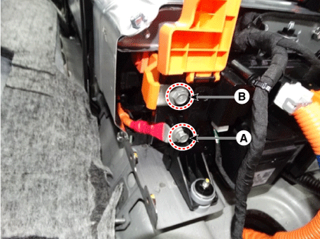
Disconnect the high voltage power cable [+] (A) and high voltage cable [-] (B) after loosening the mounting bolts.
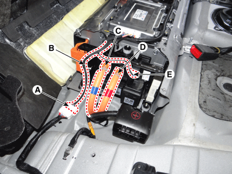
Disconnect the BMS ECU extension connector (A), battery current sensor connector (B), inverter power connector [-] (C), inverter power connector [+] (D), and PRA connector (E).
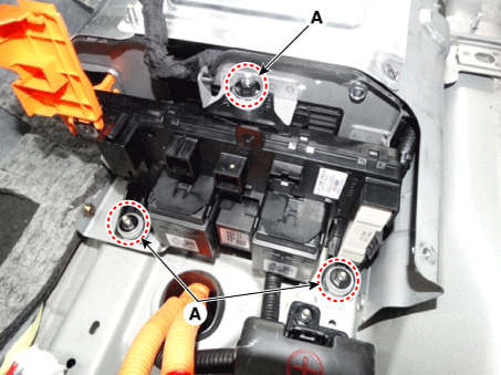
Remove the power relay connector after loosening the mounting nuts (A).
Power relay assembly mounting nut :
7.8 - 11,8 N·m

Installation
Install the power relay assembly in the reverse order of removal.