Repair procedures
Removal
Shut off the high voltage circuit.
(Refer to Hybrid Control System - “High Voltage Shutoff Procedure”)
Remove the rear seat cushion.
(Refer to Body - "Rear Seat Assembly")
Remove the rear door scuff trim.
(Refer to Body - "Door Scuff Trim")
Remove the cooling duct.
(Refer to High Voltage Battery Cooling System - "Cooling Duct")
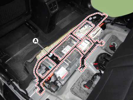
Remove the upper frame (A) after loosening the mounting bolts and nuts.
High voltage battery system assembly upper frame mounting bolt :
19.6 - 29 N·m
High voltage battery system assembly upper frame mounting nut (M8) :
19.6 - 29 N·m
High voltage battery system assembly upper frame mounting nut (M6) :
7.8 - 11,8 N·m
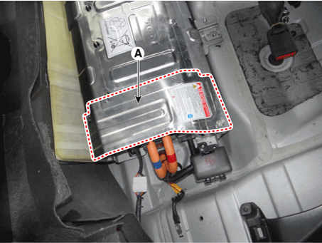
Remove the high voltage battery rear cover (A) after loosening the mounting bolts and nuts.
High voltage battery rear cover mounting bolt / nut :
7.8 - 11,8 N·m
Remove the high voltage battery front cover (A) after loosening the mounting bolts and nuts.
High voltage battery front cover mounting bolt / nut :
7.8 - 11,8 N·m

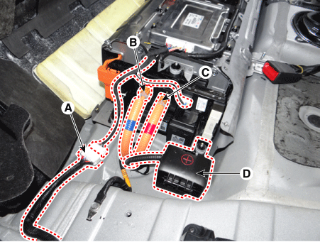
Disconnect the BMS ECU extension wiring connector (A), inverter power connector [-] (B) and inverter power connector [+] (C)
Remove the 12V junction box (D) after loosening the mounting nuts.
Unfasten the high voltage battery system assembly (A) in the direction of arrow.
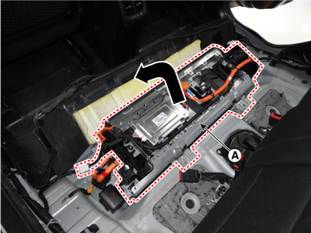
Disconnect the auxiliary 12V battery wiring harness (A) after releasing the fixing hook.
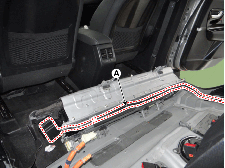
Remove the high voltage battery system assembly (A) from the vehicle.
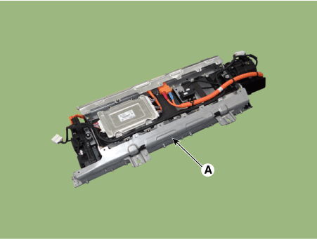
Installation
Install the high voltage battery system in the reverse order of removal.