Brake System
Electric Parking Brake (EPB) Schematic Diagrams
In this manual: Brake System
~1min read
EPB Circuit Diagram (1)
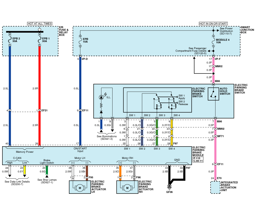
EPB Circuit Diagram (2)
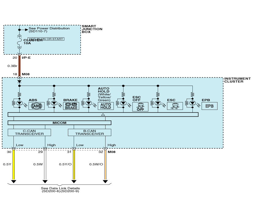
EPB Connector Input/Output
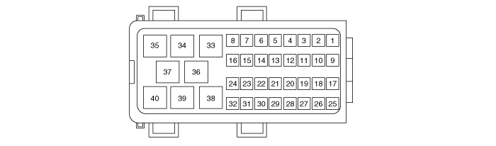
| Pin | Description | Pin | Description | ||
| 1 | - | - | 21 | - | - |
| 2 | - | - | 22 | D | C-CAN (Low) |
| 3 | - | - | 23 | W | C-CAN (High) |
| 4 | - | - | 24 | W | Electric Parking Brake Switch (SW1) |
| 5 | - | - | 25 | L/O | Electric Parking Brake Switch (SW2) |
| 6 | - | 26 | GO | Electric Parking Brake Switch (SW3) | |
| 7 | - | - | 27 | EY | Electric Parking Brake Switch (SW4) |
| 8 | - | - | 28 | - | - |
| 9 | - | 29 | - | - | |
| 10 | - | - | 30 | - | - |
| 11 | - | - | 31 | - | - |
| 12 | - | - | 32 | - | - |
| 13 | - | - | 33 | B | Ground (GF06) |
| 14 | - | - | 34 | B | Ground (GF06) |
| 15 | - | - | 35 | or | Electric Parking Brake Actuator RH (+) |
| 16 | - | 36 | Br | Electric Parking Brake Actuator (-) | |
| 17 | L | Smart Junction Box (Fuse - EPB) |
37 | Gr | Electric Parking Brake Actuator RH (-) |
| 18 | - | - | 38 | W | Electric Parking Brake Actuator (+) |
| 19 | - | - | 39 | R | Fuse and Relay Box E/R (FUSE - EPB 1) |
| 20 | G | Stop Lamp Switch | 40 | L | Fuse and Relay Box E/R (FUSE - EPB 2) |
Test yourself
A quick Kia Optima Hybrid Owner's Manual quiz: every answer comes with an explanation and a link to the manual page.
Was this page helpful?