In this manual: Heating, Ventilation, and Air Conditioning
40steps
~240min
5/5difficulty
Tightening torque found on this page
Done 0 of 40
Replacement
Be sure to read and observe the "General Safety Information and Caution" before performing any work on the high voltage system. Failure to follow the safety instructions may result in serious electrical injury.
Before performing any work, be sure to disconnect high voltage related to the high voltage system (refer to "High Voltage Disconnection Procedure"). Failure to follow safety instructions may result in serious electric shock.
Charge the refrigerant using the refrigerant recovery/recycling/charging station.
Disconnect the negative (-) battery terminal.
Disconnect the high-voltage circuit. (Refer to Electric Vehicle Battery System - "High Voltage Disconnection Procedure")
Remove the upper hood cover. (Refer to Body - "Upper Cover Panel")
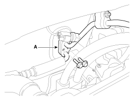
Remove the pipe (A) after loosening the mounting bolts.
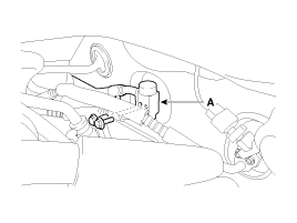
Remove the expansion valve (A) after loosening the mounting bolts on the evaporator core.
Tightening torque: 7.8 ~ 11.7 N·m
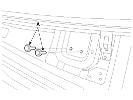
Loosen the hood cross member mounting bolts (A).
Remove both front seat assemblies. (Refer to Body - "Front Seat Assembly")
Remove the floor console assembly. (Refer to Body – Floor Console Assembly)
Remove the emergency pad lower panel. (Refer to Body - "Emergency Pad Lower Panel")
Remove the glove box housing. (Refer to Body - "Glove Box Housing")
Remove the center airbag panel. (Refer to Body - "Center Airbag Panel")
Remove both sides of the front pillar garnish. (Refer to Body - "Front Pillar Garnish")
Remove both hood side trim panels. (Refer to Body - "Hood Side Trim")
Remove the lower steering column cover panel. (Refer to Body - "Steering Column Cover Panel")
Remove the steering wheel. (Refer to Steering System - "Steering Wheel")
Remove the combination switch. (Refer to Body Electrical System - "Combination Switch")
Lower the steering column after loosening the mounting bolts. (Refer to Steering System - "Steering Column and Shaft")
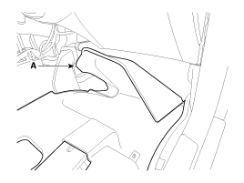
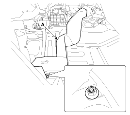
Remove the rear duct assembly (A). [LH]
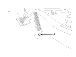
Remove the accelerator pedal fixing cap (A).
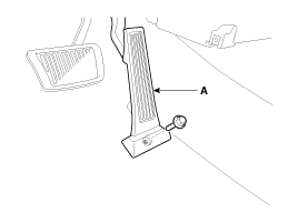
Remove the accelerator pedal (A) after loosening the mounting bolt.
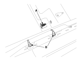
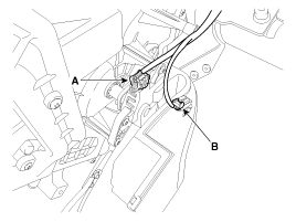
Remove the floor carpet clip (A) and the floor wire clip (B).
Fold the front floor carpet back.
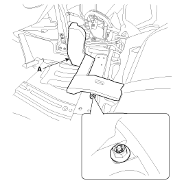
Remove the rear duct assembly (A) after loosening the mounting nut.
[RH]
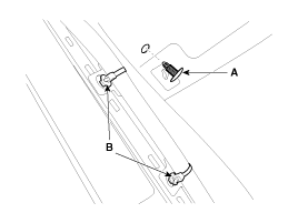
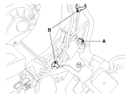
Remove the floor carpet clip (A) and the floor wire clip (B).
Fold the front floor carpet (A) back.
Remove the rear duct assembly (A) after loosening the mounting nut.
Remove the shift lever assembly. (Refer to Automatic Transmission System - "Shift Lever")
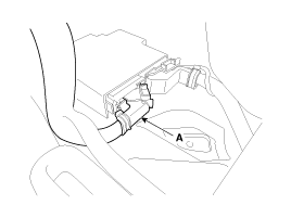
Disconnect the connector (A) of the SRS control module (SRSCM).
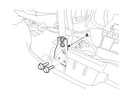
After loosening the mounting bolts and nuts, remove the hood crossmember center bracket (A).
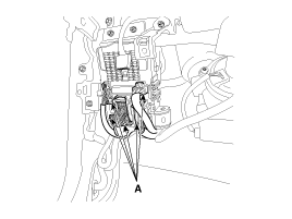
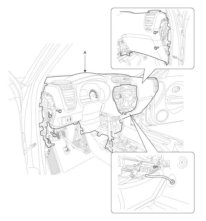
Disconnect the junction block connectors in the cabin (A).
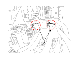
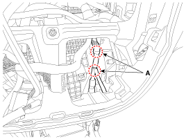
Remove the junction block mounting clips (A) from the passenger compartment.
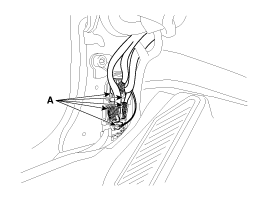
Disconnect the multi-box connectors (A). [Driver][Passenger]
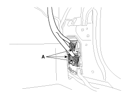
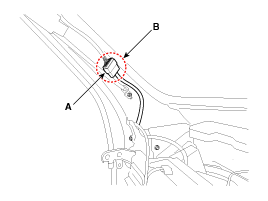
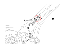
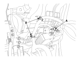
Disconnect the connector (A) and mounting clips (B) on the front pillar. [Driver][Passenger]
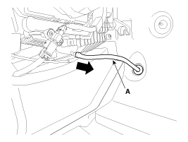
Remove the drain hose (A).
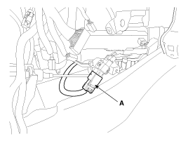
Disconnect the PTC heater high voltage cable (A).
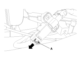
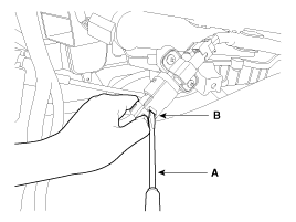
How to Press the Lock Pin of the PTC Heater High Voltage Cable
Pull the lock pin (A) in the direction of the arrow.
While pressing the lock pin with a flat-tip screwdriver (A) into the hole (B), pull out the connector.
Remove the main cover and cross member (A) completely by loosening the bolts.
Disconnect the connectors of the heater and blower unit.
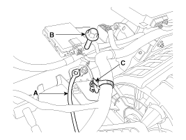
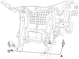
Remove the high voltage heater ground (A) by loosening the mounting bolt (B) and the fixing clip (C).
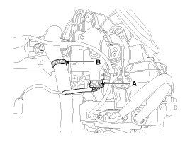
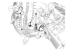
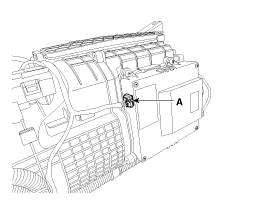
Remove the fixing clip (B) after disconnecting the intake actuator connector (A).
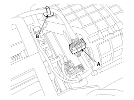
Remove the fixing clip (B) after disconnecting the blower unit connector (A).
Remove the fixing bracket (B) after disconnecting the PWM unit connector (A).
Remove the fixing clip (B) after disconnecting the blower motor connectors (A).
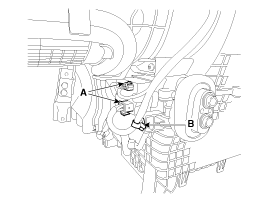
Disconnect the temperature control actuator connector (A) and the duct sensor connector (B).
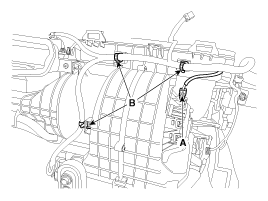
Remove the retaining clip (B) after disconnecting the mode control actuator connectors (A).
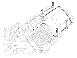
Remove the fixing clips (B) after loosening the fixing screw of the VESS unit (A).
Remove the mounting clips (A).
Loosen the heater and blower unit mounting bolts (A).
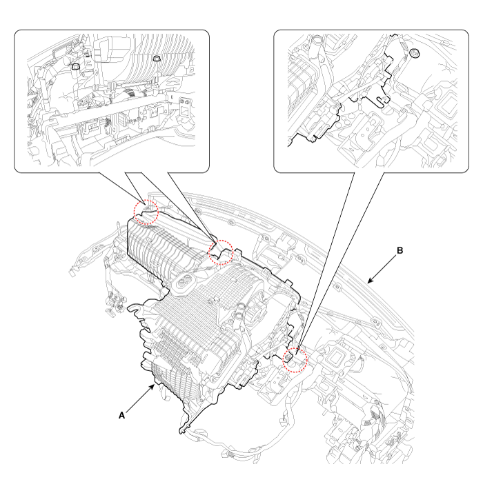
Remove the heater and blower unit (A) from the protector (B) after loosening the mounting nuts.
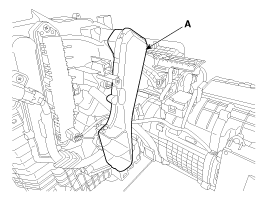
Remove the duct (A) after loosening the fixing screw.
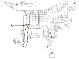
Disconnect the connector (B). Then remove the high voltage line guide (A) after loosening the fixing screws.
Disconnect the PTC heater high voltage connector (A).
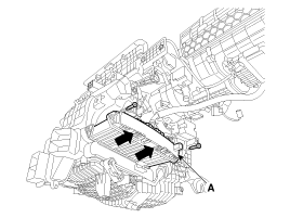
Remove the PTC heater high voltage unit (A) after loosening the fixing screws.
Remove the PTC high voltage heater core (A) after loosening the fixing screws.
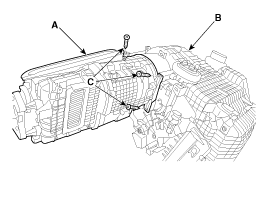
Separate the blower unit (A) from the heater unit (B) after loosening the fixing screws (C).
Install in the reverse order of removal.
?
Test yourself
A quick Kia Soul EV Owner's Manual quiz: every answer comes with an explanation and a link to the manual page.