Brake System
Brake Pedal Repair Procedures
In this manual: Brake System
47steps
~282min
5/5difficulty
Done 0 of 47
Removal [LH]
- Turn the ignition switch OFF and disconnect the negative (-) battery cable.
- Remove the lower instrument panel cover. (Refer to Body - "Lower Instrument Panel Cover")
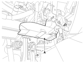
- Remove the shower duct (A).
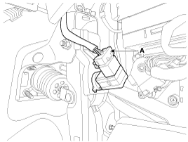
- Disconnect the stop lamp switch connector (A).
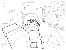
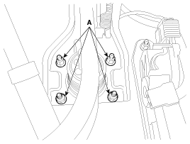
- Remove the brake pedal mounting bolt (A).
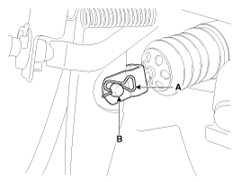
- Remove the lock pin (A) and the flat head pin (B).
- Loosen the brake pedal assembly mounting nuts, then remove the brake pedal assembly.
Removal [RHD]
- Turn the ignition switch OFF and disconnect the negative (-) battery cable.
- Remove the lower instrument panel cover. (Refer to Body - "Lower Instrument Panel Cover")
- Remove the junction box.
- Disconnect the stop lamp switch connector (A).
- Remove the brake pedal mounting bolt (A).
- Remove the lock pin (A) and the flat head pin (B).
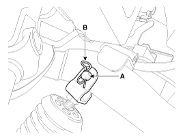
- Loosen the brake pedal assembly mounting nuts, then remove the brake pedal assembly.
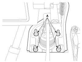
Inspection
- Inspect the bushing for wear.
- Inspect the brake pedal for bending or twisting.
- Inspect the brake pedal return spring for damage.
- Inspect the stop lamp switch.
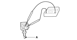
- Connect a circuit tester to the stop lamp switch connector and check for continuity when the stop lamp switch plunger is pressed and when it is released.
- The stop lamp switch is normal if there is no continuity when the plunger (A) is pressed.
Installation [LH Steering]
- Temporarily tighten the bracket mounting bolt (A) on the dash panel.
- Securely install the brake booster and the brake pedal mounting nuts (A).
Tightening torque: 16.7 ~ 26 N·m
- Securely tighten the bolt (A) on the dash panel.
Tightening torque: 16.7 ~ 26 N·m
- Install the stopper pin (A) and the flat head pin (B).
- Securely install the stop lamp switch.
- Connect the connector of the brake light switch (A).
- Adjust the brake pedal height and free play.
- After installing the brake pedal, check the brake pedal operation.
- Install the shower channel (A).
- Install the lower crash pad panel. (Refer to Body - "Lower Crash Pad Panel").
- Connect the negative battery cable.
Installation [RH Steering]
- Temporarily tighten the bracket mounting bolt (A) on the dash panel.
- Securely install the brake booster and the brake pedal mounting nuts (A).
Tightening torque: 16.7 ~ 26 N·m
- Securely tighten the bolt (A) on the dash panel.
Tightening torque: 16.7 ~ 26 N·m
- Install the stopper pin (A) and the flat head pin (B).
- Securely install the stop lamp switch.
- Connect the connector of the brake light switch (A).
- Adjust the brake pedal height and free play.
- After installing the brake pedal, check the brake pedal operation.
- Install the junction box. (Refer to Body Electrical System - Relay Box)
- Install the lower crash pad panel. (Refer to Body - "Lower Crash Pad Panel").
- Connect the negative battery cable.
Adjustment
Brake Light Switch Clearance Adjustment
If the clearance between the stop lamp switch and the bracket is not 1.0 - 2.0 mm (0.04 - 0.08 in.), adjust as described below.- Disconnect the stop lamp switch connector (A).
- Pull the lock plate (A) as shown by the arrow.
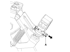
- Turn the stop lamp switch 45° counterclockwise and remove it.
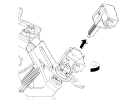
- Hold the brake pedal arm and fully insert the brake light switch so that the contact part is hidden.
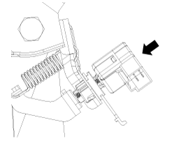
- After inserting, turn the lock switch (A) 45° clockwise, then assemble the retainer plate (B) by pressing it.
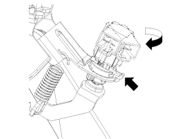
- Check the clearance between the stop lamp switch and the bracket.
Stop lamp switch clearance: 1.0-2.0 mm (0.04-0.08 in.)
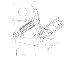
- Connect the stop lamp switch connector.
Test yourself
A quick Kia Cee'd quiz: every answer comes with an explanation and a link to the manual page.
Was this page helpful?