Drive Shaft and Axle
Front Axle Assembly
In this manual: Drive Shaft and Axle
23steps
~143min
5/5difficulty
1special tools
Done 0 of 23
Components and Component Location
Components

| 1. Snap Ring 2. Bearing 3. Axle Assembly 4. Brake Disc Dust Cover 5. Wheel Hub Assembly |
6. Wheel Brake Disc 7. Brake Disc Mounting Screw 8. Wheel/Tire 9. Wheel Nut |
Repair Procedures
Removal
- Remove the front/rear wheel tire (A).
Tightening torque: 107.9–128 N·m

- Remove the brake caliper mounting bolts (A) and hang the brake caliper with wire.
Tightening torque: 78.4–98 N·m

- Unstake the drive shaft hub nut lock by tapping a chisel with a hammer.

- Remove the lock nut from the front axle.
Tightening torque: 274.6–294 N·m

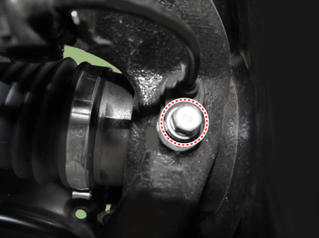
- Loosen the bolt and remove the wheel speed sensor.
Tightening torque: 6.9–10.8 N·m
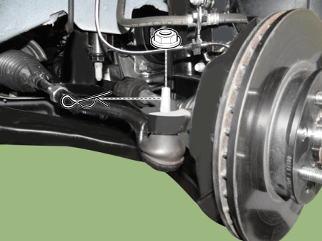
- Remove the cotter pin and nut from the steering tie rod end ball joint.
Tightening Torque: 24.5–34 N·m
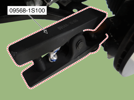
- Disconnect the steering tie rod end ball joint from the steering knuckle using SST (09568-1S100).
- Remove the lower arm bolt and nut (A).
Tightening torque: 58.8–71 N·m

- Remove the front lower arm from the front steering knuckle using SST (0K545-A9100).
- After removing the bolts from the front steering knuckle, install and tighten the body support bolt (A).

- Insert the auxiliary body (B) between the front steering knuckle and the auxiliary body bolt.
- Tighten the auxiliary body bolt (C) to increase the front steering knuckle clearance.

- Install the safety wire.

- Install the main body (A) between the front strut and the lower arm.
- To prevent the main body from coming off, install the locking clip (B) next to the main body.

- After installing the body, turn the handle (A) clockwise until the clip engages the lower arm.

- Slowly tighten the main body bolt (A) and remove the lower arm from the front steering knuckle.

- After removing the bolts from the front steering knuckle, install and tighten the body support bolt (A).
- Loosen the screw and remove the brake disc.
Tightening torque: 4.9 - 5.9 N·m

- Loosen the front strut bolts and nuts and remove the steering knuckle assembly (A).
Tightening torque: 98.0–118 N·m

Inspection
- Check the hub for cracks and worn splines.
- Check the brake disc for scratches and damage.
- Inspect the knuckle for cracks.
- Check the bearing for cracks or damage.
Disassembly
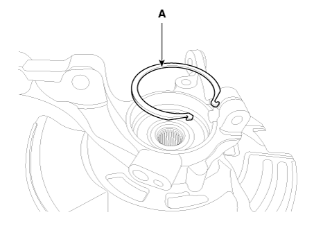
- Remove the snap ring (A).
- Remove the hub assembly from the steering knuckle assembly.
- Install the front steering knuckle assembly (A) on the press.
- Install a suitable adapter (B) onto the hub shaft assembly.
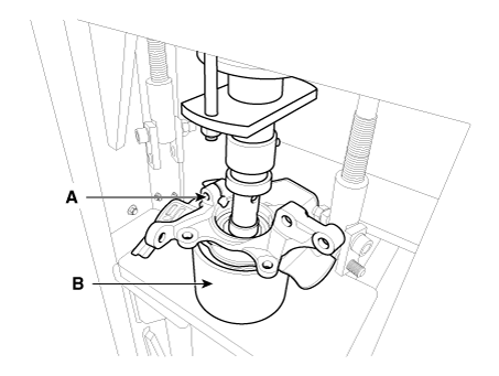
- Remove the hub bearing inner race from the hub assembly.
- Install the wheel hub bearing inner race remover (A) onto the hub assembly.
- Secure the hub assembly and the remover (A) on a suitable adapter (B).
- Install a suitable adapter (C) onto the hub assembly shaft.
- Using a press, remove the wheel hub bearing inner race (D) from the hub assembly.
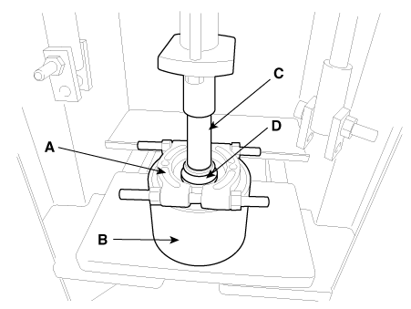
- Remove the hub bearing outer race from the steering knuckle assembly.
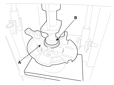
- Secure the steering knuckle assembly (A) on a suitable adapter (B).
- Install a suitable adapter (C) onto the wheel hub bearing outer race.
- Using a press, remove the wheel hub bearing outer race from the steering knuckle assembly.

- Replace the hub bearing with a new one.
Installation
- Install the hub bearing onto the steering knuckle assembly.
- Secure the steering knuckle assembly (A) in the press.
- Install a new hub bearing onto the steering knuckle assembly (A).
- Install a suitable adapter (B) onto the hub bearing.
- Using a press, install the wheel hub bearing into the steering knuckle assembly.
- Install the hub assembly onto the steering knuckle assembly.
- Secure the hub assembly (A) on a suitable adapter.
- Install the steering knuckle assembly (B) onto the hub assembly (A).
- Install a suitable adapter (C) onto the wheel hub bearing.
- Press to install the hub assembly (A) onto the steering knuckle assembly (B).
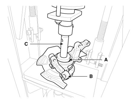
- Install the snap ring (A).
Test yourself
A quick Kia Picanto JA quiz: every answer comes with an explanation and a link to the manual page.
Was this page helpful?