Instrument cluster inspection
Inspect the speedometer by setting it in the input/output check mode DTC 12.
Using a speedometer tester1. Adjust the tire air pressure to the specification.
2. Using a speedometer tester, verify that the speedometer indication is within the allowable ranges shown below.
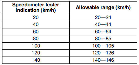
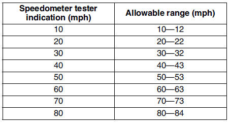
3. Verify that fluctuation of the speedometer needle is within the allowable range.
- If the speedometer needle does not move or the indication is outside of the allowable range, inspect the ABS (ABS/TCS) HU/CM (vehicles with ABS (ABS/TCS), DSC HU/CM (vehicles with DSC), PCM (vehicles without ABS) and related wiring harness.
Tachometer Using the input/output check mode- If the ABS (ABS/TCS) HU/CM (vehicles with ABS (ABS/TCS), DSC HU/CM (vehicles with DSC), PCM (vehicles without ABS) and related wiring harness are normal, replace the instrument cluster.
Needle fluctuation allowable range Within 3 km/h
Inspect the tachometer by setting it in the input/output check mode DTC 13.
Using the SSTs (WDS or equivalent) Caution- If the engine speed exceeds the allowable range, the engine could be damaged. Therefore, when inspecting the tachometer, do not allow the engine speed to exceed the allowable range indication Bon the tachometer.
(WDS or equivalent) to the vehicle DLC-2 16-pin connector.
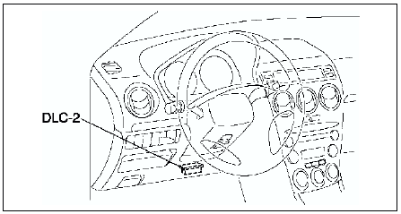
2. Access and monitor PIDs by SSTs
(WDS or equivalent).
Fuel GaugeInspect the fuel gauge by setting it in the input/output check mode DTC 23.
Water Temperature GaugeInspect the water temperature gauge by setting it in the input/output check mode DTC 25.
Test yourself
A quick Mazda 6 quiz: every answer comes with an explanation and a link to the manual page.