Diagnosis and repair workflow
Gasoline engine models
GASOLINE ENGINE MODELS : Work FlowOVERALL SEQUENCE

DETAILED FLOW
1.PRELIMINARY INSPECTIONPerform the preliminary inspection. Refer to CHG-17, "Inspection Procedure".
Models with battery current sensor>>GO TO 2.
Models without battery current sensor>>GO TO 3.
2.STOP POWER GENERATION VOLTAGE VARIABLE CONTROL SYSTEMStop the operation of the power generation voltage variable control in either of the following procedures.
• After selecting “ENGINE” of “SELECT SYSTEM” using CONSULT-III, set the DUTY value of “ALTERNATOR DUTY” to 0 % by selecting “ALTERNATOR DUTY” of “Active Test”. Continue “Active Test” until the end of inspection. (When the DUTY value is 0 or 100 %, the normal power generation is performed according to the characteristic of the IC regulator of the alternator.) • Turn the ignition switch OFF, and disconnect the battery current sensor connector. [However, DTC (P1550 - P1554) of the engine might remain. After finishing the inspection, connect the battery current sensor connector and erase the self-diagnostic results history of the engine using CONSULT-III.] >> GO TO 3.
3.INSPECTION WITH CHARGE WARNING LAMP (IGNITION SWITCH IS ON)Turn the ignition switch ON.
Does the charge warning lamp illuminate? YES >> GO TO 4.
NO >> GO TO 11.
4.INSPECTION WITH CHARGE WARNING LAMP (IDLING)Start the engine and run it at idle.
Does the charge warning lamp turn OFF? YES >> GO TO 5.
NO >> GO TO 6.
5.INSPECTION WITH CHARGE WARNING LAMPIncrease and maintain the engine speed at 2,500 rpm.
Does the charge warning lamp illuminate? YES >> GO TO 8.
NO >> INSPECTION END
6.“L” TERMINAL CIRCUIT (SHORT) INSPECTIONCheck “L” terminal circuit (short). Refer to CHG-23, "Diagnosis Procedure".
Is the inspection result normal? YES >> GO TO 7.
NO >> Repair as needed.
7.“S” TERMINAL CIRCUIT INSPECTIONCheck “S” terminal circuit. Refer to CHG-24, "Diagnosis Procedure".
Is the inspection result normal? YES >> GO TO 8.
NO >> Repair as needed.
8.MEASURE “B” TERMINAL VOLTAGEStart engine. When keeping engine running at 2,500 rpm, measure “B” terminal voltage.
What voltage does the measurement result show? Less than 13.0 V>>GO TO 9.
More than 16.0 V>>Replace IC voltage regulator.
9.“B” TERMINAL CIRCUIT INSPECTIONCheck “B” terminal circuit. Refer to CHG-20, "Diagnosis Procedure".
Is the inspection result normal? YES >> GO TO 10.
NO >> Repair as needed.
10.DISASSEMBLE AND CHECK ALTERNATORCheck the following conditions.
• Rotor coil
• Rotor slip ring
• Brush
• Stator coil
Refer to CHG-29, "HR16DE : Inspection" (HR16DE), CHG-33, "MR16DDT : Inspection" (MR16DDT).
Are these normal? YES >> Replace IC voltage regulator and/or diode assembly.
NO >> Repair as needed.
11.INSPECTION WITH CHARGE WARNING LAMP (IGNITION SWITCH IS ON) 1. Disconnect alternator connector and ground “L” harness side.2. Turn the ignition switch ON.
Does the charge warning lamp illuminate? YES >> GO TO 12.
NO >> GO TO 13.
12.DISASSEMBLE AND CHECK ALTERNATORCheck the following conditions.
• Rotor coil
• Rotor slip ring
• Brush
Refer to CHG-29, "HR16DE : Inspection" (HR16DE), CHG-33, "MR16DDT : Inspection" (MR16DDT).
Are these normal? YES >> Replace IC voltage regulator.
NO >> Repair as needed.
13.CHECK “L” TERMINAL CIRCUIT (OPEN)Check “L” terminal circuit (open). Refer to CHG-21, "Diagnosis Procedure".
>> Repair as needed.
Diesel engine models
DIESEL ENGINE MODELS : Work FlowOVERALL SEQUENCE
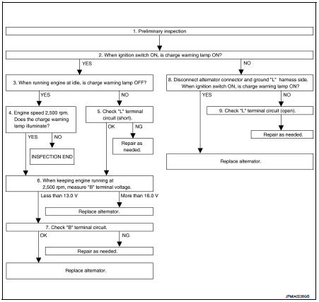
DETAILED FLOW
1.PRELIMINARY INSPECTIONPerform the preliminary inspection. Refer to CHG-17, "Inspection Procedure".
>> GO TO 2.
2.INSPECTION WITH CHARGE WARNING LAMP (IGNITION SWITCH IS ON)Turn the ignition switch ON.
Does the charge warning lamp illuminate? YES >> GO TO 3.
NO >> GO TO 8.
3.INSPECTION WITH CHARGE WARNING LAMP (IDLING)Start the engine and run it at idle.
Does the charge warning lamp turn OFF? YES >> GO TO 4.
NO >> GO TO 5.
4.INSPECTION WITH CHARGE WARNING LAMP (ENGINE AT 2,500 RPM)Increase and maintain the engine speed at 2,500 rpm.
Does the charge warning lamp illuminate? YES >> GO TO 6.
NO >> INSPECTION END
5.“L” TERMINAL CIRCUIT (SHORT) INSPECTIONCheck “L” terminal circuit (short). Refer to CHG-23, "Diagnosis Procedure".
Is the inspection result normal? YES >> GO TO 6.
NO >> Repair as needed.
6.MEASURE “B” TERMINAL VOLTAGEEngine start. When keeping engine running at 2,500 rpm, measure “B” terminal voltage.
What voltage does the measurement result show? Less than 13.0 V>>GO TO 7.
More than 16.0 V>>Replace alternator.
7.“B” TERMINAL CIRCUIT INSPECTIONCheck “B” terminal circuit. Refer to CHG-20, "Diagnosis Procedure".
Is the inspection result normal? YES >> Replace alternator.
NO >> Repair as needed.
8.INSPECTION WITH CHARGE WARNING LAMP (IGNITION SWITCH IS ON) 1. Disconnect alternator connector and ground “L” harness side.2. Turn the ignition switch ON.
Does the charge warning lamp illuminate? YES >> Replace alternator.
NO >> GO TO 9.
9.CHECK “L” TERMINAL CIRCUIT (OPEN)Check “L” terminal circuit (open). Refer to CHG-21, "Diagnosis Procedure".
>> Repair as needed.