How to select piston and bearing
Description
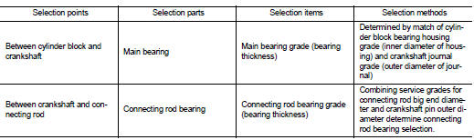
• The identification grade stamped on each part is the grade for the dimension measured in new condition. This grade cannot apply to reused parts. • For reused or repaired parts, measure the dimension accurately. Determine the grade by comparing the measurement with the values of each selection table.
• For details of the measurement method of each part, the reuse standards and the selection method of the selective fitting parts, refer to the text.
Connecting Rod Bearing
WHEN NEW CONNECTING ROD AND CRANKSHAFT ARE USED
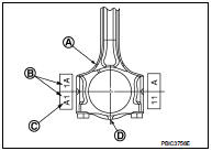
1. Apply connecting rod big end diameter grade stamped (C) on connecting rod side face to the row in the “Connecting Rod Bearing Selection Table”.
A : Oil hole
B : Cylinder number
D : Front mark
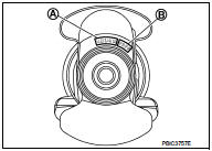
2. Apply crankshaft pin journal diameter grade stamped (B) on crankshaft front side to the column in the “Connecting Rod Bearing Selection Table”.
A : Main journal diameter grade (No. 1 to 5 from left) B : Crankshaft pin journal diameter grade (No. 1 to 4 from left)
3. Read the symbol at the cross point of selected row and column in the “Connecting Rod Bearing Selection Table”.
4. Apply the symbol obtained to the “Connecting Rod Bearing Grade Table” to select connecting rod bearing.
WHEN CONNECTING ROD AND CRANKSHAFT ARE REUSED
1. Measure the dimensions of the connecting rod big end diameter and crankshaft pin journal diameter individually.
Refer to EM-236, "Inspection". 2. Apply the measured dimension to the “Connecting Rod Bearing Selection Table”. 3. Read the symbol at the cross point of selected row and column in the “Connecting Rod Bearing Selection Table”.4. Apply the symbol obtained to the “Connecting Rod Bearing Grade Table” to select connecting rod bearing.
Connecting Rod Bearing Selection Table
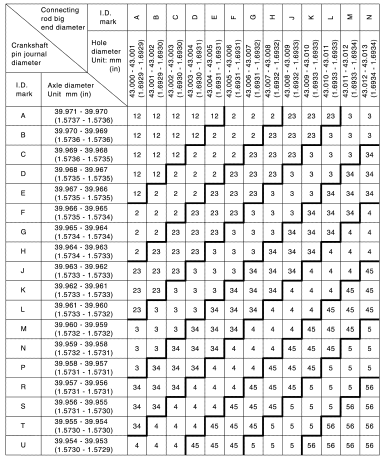
Connecting Rod Bearing Grade Table
Connecting Rod Bearing Grade Table : Refer to EM-258, "Connecting Rod Bearing".
Undersize Bearings Usage Guide • When the specified connecting rod bearing oil clearance is not obtained with standard size connecting rod bearings, use undersize (US) bearings.• When using undersize (US) bearing, measure the connecting rod bearing inner diameter with bearing installed, and grind the crankshaft pin so that the connecting rod bearing oil clearance satisfies the standard.
CAUTION:In grinding crankshaft pin to use undersize bearings, keep the fillet R (A) [0.8 - 1.2 mm (0.031 - 0.047 in)].
Bearing undersize table: Refer to EM-258, "Connecting Rod Bearing".

Main Bearing
HOW TO SELECT MAIN BEARING
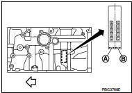
When New Cylinder Block and Crankshaft Are Used 1. “Main Bearing Selection Table” rows correspond to main bearing housing grade on left side of cylinder block.
A : Basic stamp mark  : Engine front
• If there is a corrected stamp mark (B) on cylinder block, use it as a correct reference.
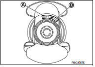
2. Apply main journal diameter grade stamped on crankshaft front side to column in the “Main Bearing Selection Table”.
A : Main journal diameter grade (No. 1 to 5 from left) B : Crankshaft pin journal diameter grade (No. 1 to 4 from left)
3. Read the symbol at the cross point of selected row and column in the “Main Bearing Selection Table”.
4. Apply the symbol obtained to the “Main Bearing Grade Table” to select main bearing.
NOTE:
Service part is available as a set of both upper and lower.
2. Apply the measured dimension to the “Main Bearing Selection Table”.
3. Read the symbol at the cross point of selected row and column in the “Main Bearing Selection Table”.4. Apply the symbol obtained to the “Main Bearing Grade Table” to select main bearing.
Main Bearing Selection Table
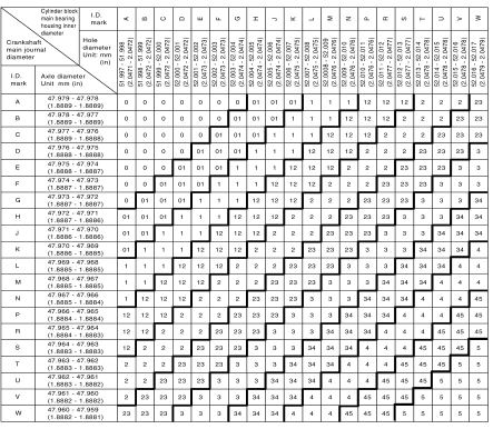
Main Bearing Grade Table
Main Bearing Grade Table : Refer to EM-257, "Main Bearing".
Use Undersize Bearing Usage Guide • When the specified main bearing oil clearance is not obtained with standard size main bearings, use undersize (US) bearing.• When using undersize (US) bearing, measure the main bearing inner diameter with bearing installed, and grind main journal so that the main bearing oil clearance satisfies the standard.
CAUTION:In grinding crankshaft main journal to use undersize bearings, keep fillet R (A) [0.8 - 1.2 mm (0.031 - 0.047 in)].
Bearing undersize table: Refer to EM-257, "Main Bearing".
