SRS Airbag

Spiral cable

In this manual: SRS Airbag
Foreword — 1General information — 45Engine Mechanical MR16DDT — 61Engine Mechanical HR16DE — 52Engine Mechanical K9K — 46Engine Lubrication System MR16DDT — 18Engine Lubrication System HR16DE — 14Engine Lubrication System K9K — 11Engine Cooling System MR16DDT — 28Engine Cooling System HR16DE — 29Engine Cooling System K9K — 24Engine Control System MR16DDT — 163Engine Control System HR16DE — 115Engine Control System K9K — 129Fuel System MR16DDT — 13Fuel system HR16DE — 11Fuel system K9K — 12Exhaust system MR16DDT — 7Exhaust system HR16DE — 10Exhaust system K9K — 7Starting system — 24Accelerator control system — 6Clutch — 25Driveline transfer: TY21B — 77Driveline rear propeller Shaft: 3Fφ16-ETJ75 — 12Driveline rear final drive: RTVS — 31Transaxle & transmission 5MT: RS5F92R — 31Transaxle & transmission 6MT: RS6F94R — 30Transaxle & transmission CVT: RE0F10B — 93Transaxle & transmissioN CVT: RE0F11A — 103Front Axle MR16DDT — 18Front Axle HR16DE — 17Front Axle K9K — 17Rear Axle 2WD — 6Rear Axle 4WD — 13Front Suspension — 21Rear Suspension 2WD — 13Rear Suspension 4WD — 17Road Wheels & Tires — 6Brake System LHD — 24Brake System RHD — 24Parking Brake System — 8Brake Control System without ESP — 44Brake Control System with ESP — 63Steering System — 14Steering Control System — 27Seat Belt — 8SRS Airbag — 24SRS Airbag Control System — 93Ventilation System — 11Heater & Air Conditioning System HR16DE — 28Heater & Air Conditioning System MR16DDT — 28Heater & Air Conditioning Control System Type 1 — 49Heater & Air Conditioning Control System Type 2 — 51Heater & Air Conditioning Control System Type 3 — 32Heater & Air Conditioning Control System Type 4 — 40Heater & Air Conditioning Control System Type 5 — 21Interior — 16Instrument Panel — 10Seat — 18Door & Lock Type 1 — 83Door & Lock type 2 — 80Door & Lock type 3 — 65Door & Lock type 4 — 60Security Control System with intelligent key system — 82Security Control System without intelligent key system — 41Glass & Window System — 15Power Window Control System — 28Body Repair — 13Exterior — 20Mirrors — 26Exterior Lighting System Halogen type — 51Interior Lighting System — 24Wiper & Washer — 45Defogger — 31Horn — 4Power Outlet — 4Body Control System With intelligent key system — 21Body Control System Without intelligent key system — 23LAN system can fundamental — 6LAN system can — 31LAN System can system (type 1) — 1LAN System can system (type 2) — 1LAN System can system (type 3) — 1LAN System can system (type 4) — 1LAN System can system (type 5) — 1LAN System can system (type 6) — 1LAN System can system (type 7) — 2LAN System can system (type 8) — 1LAN System can system (type 9) — 1LAN System can system (type 10) — 1LAN System can system (type 11) — 1Power Control System IPDM E/R (with I-key) — 14Power Control System IPDM E/R (without I-key) — 14Power Control System Power distribution system — 25Charging System — 22Power Supply, Ground & Circuit Elements — 20Meter, Warning Lamp & Indicator — 33Warning Chime System — 22Audio, Visual & Navigation System Audio without navigation — 30Audio, Visual & Navigation System Audio with navigation — 33Audio, Visual & Navigation System NISSAN dynamic control system — 22Cruise Control System — 1Drive Mode System — 10Maintenance — 14
~3min read

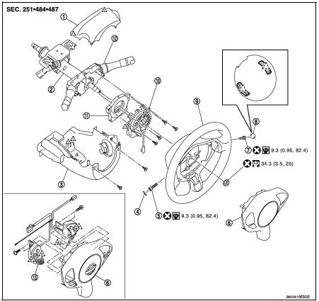
Exploded View

1. Steering column upper cover

1. Steering column upper cover 2. Steering column assembly 3. Steering column lower cover 4. Side lid LH
5. TORX bolt
6. Driver air bag module 7. TORX bolt
8. Side lid RH
9. Steering wheel
10. Spiral cable
11. Steering angle sensor 12. Combination switch
13. Steering switch

: Do not reuse: Pawl
: N·m (kg-m, in-lb): Do not reuse
: N·m (kg-m, ft-lb): N·m (kg-m, in-lb)
Removal and Installation: N·m (kg-m, ft-lb)


Removal and Installation

WARNING:
• Before servicing, turn ignition switch OFF, disconnect battery negative terminal and wait 3 minutes or more.

• Never use the air tools or electric tools for servicing.

REMOVAL

1. Remove driver air bag module. Refer to SR-13, "Removal and Installation". 2. Remove steering wheel. Refer to ST-9, "Removal and Installation". 3. Remove steering column upper cover and steering column lower cover. Refer to IP-13, "Removal and Installation".

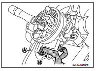
4. Disconnect the spiral cable body side harness connectors (A), (B) and steering angle sensor harness connectors (C).

NOTE

:
Disconnect the spiral cable body side harness connector (B) after removing the spiral cable (A).
5. Remove the spiral cable fixing screws.

5. Remove the spiral cable fixing screws.

6. Remove the spiral cable fixing pawls with remover tool (A).
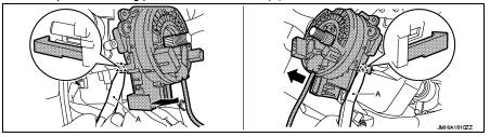
: Pawl

CAUTION:: Pawl


CAUTION:
Remove pawls slowly so that they are not damaged.

7. Remove the steering angle sensor. Refer to BRC-236, "Removal and Installation".

CAUTION:
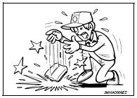
• Never impact the spiral cable.

• Replace the spiral cable if it is dropped or sustains an impact.
• Never disassemble the spiral cable.

• Never disassemble the spiral cable. • Never apply lubricant to the spiral cable.

• Never allow oil, grease, detergent, or water to come in contact with the spiral cable.

INSTALLATION

Note the following items, and then install in the reverse order of removal.

CAUTION:
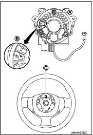
• The spiral cable may snap during steering operation if the cable is installed in an improper position. The neutral position is set as per the following.

• Carefully turn the spiral cable clockwise to the end position.

Then turn it counterclockwise (about 2 and a half turns) and stop turning at the mark (B) when the stopper insertion holes are in the same position. • The service part is installed in the neutral position by the stopper and can be set without adjusting after the stopper is removed.

• Never over turn the spiral cable or go beyond the number of turns required. (This causes the cable to snap) • Adjust the spiral cable locating pin (A) to the steering wheel locating pin hole (C).
• Fix the driver air bag module harnesses to the harness fixing

• Fix the driver air bag module harnesses to the harness fixing hook (A).
• If malfunction is detected by the air bag warning lamp, after repair or

• If malfunction is detected by the air bag warning lamp, after repair or replacement of the malfunctioning parts, reset the memory using self-diagnosis or CONSULT-III. Refer to SRC-12, "On Board Diagnosis Function" or SRC-16, "CONSULT-III Function".

• After the work is completed, check that no system malfunction is detected by air bag warning lamp.