Unit removal and installation
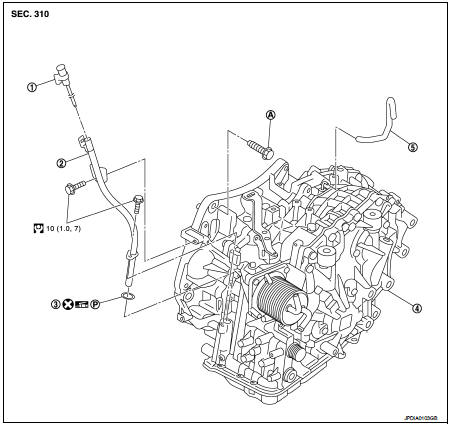
1. CVT fluid level gauge 2. CVT fluid charging pipe 3. O-ring
4. Transaxle assembly
5. Air breather hose
A. For tightening torque, refer to TM-301, "Removal and Installation".
Removal and IntallationREMOVAL
WARNING:Never remove the reservoir tank cap when the engine is hot. Serious burns could occur from highpressure engine coolant escaping from the reservoir tank. CAUTION:
• Perform this step engine is cold.
• When replacing TCM and transaxle assembly as a set, replace transaxle assembly first and then replace TCM. Refer to TM-180, "Description".
NOTE:Cap or cover any transaxle openings to prevent transaxle fluid from spiling.
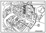
1. Disconnect the battery cable from the negative terminal. 2. Remove air breather hose. Refer to TM-281, "Removal and Installation". 3. Remove air duct (inlet). Refer to EM-26, "Removal and Installation". 4. Remove battery. Refer to PG-124, "Removal and Installation". 5. Disconnect connectors (A) and then remove bracket (1). 6. Remove air cleaner case. Refer to EM-26, "Removal and Installation". 7. Drain engine coolant. Refer to CO-11, "Draining". 8. Remove CVT fluid level gauge. 9. Remove CVT fluid charging pipe from transaxle assembly.10. Remove O-ring from CVT fluid charging pipe.
11. Disconnect fluid cooler hose from transaxle assembly. Refer to TM-298, "Removal and Installation".
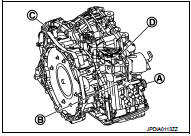
12. Disconnect following harness connector and wire harness.
• CVT unit harness connector (A). • Primary speed sensor harness connector (B). • Secondary speed sensor harness connector (C).• Transmission range switch connector (D).
13. Remove harness and clip from the transaxle assembly. 14. Remove water hose. Refer to TM-295, "Removal and Installation". 15. Remove control cable from transaxle assembly. Refer to TM- 273, "Removal and Installation". 16. Remove starter motor. Refer to STR-29, "MR16DDT : Removal and Installation".17. Remove engine under cover with power tool.
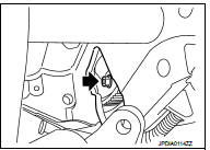
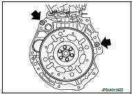
18. Turn crankshaft, and remove the four tightening nuts (  ) for
drive plate and torque converter.
When turning crankshaft, turn it clockwise as viewed from the front of the engine. 19. Remove exhaust front tube. Refer to EX-6, "Removal and Installation". 20. Separate the propeller shaft. Refer to DLN-121, "Removal and Installation". 21. Remove front drive shafts. Refer to FAX-21, "Exploded View". 22. Remove front suspension member from vehicle. Refer to FSU- 18, "Removal and Installation".
23. Remove transfer assembly from transaxle assembly with power tool. Refer to DLN-93, "Removal and Installation".
24. Support transaxle assembly with a transmission jack.
CAUTION:When setting the transmission jack, be careful not to collide against the drain plug.
25. Support engine assembly with a transmission jack.
CAUTION:When setting the transmission jack, be careful not to collide against the drain plug. 26. Remove engine mounting insulator (LH). Refer to EM-59, "4WD : Removal and Installation". 27. Remove bolts fixing transaxle assembly to engine assembly.
28. Remove transaxle assembly from vehicle.
CAUTION:• Secure torque converter to prevent it from dropping.
• Secure transaxle assembly to a transmission jack.
29. Remove heater thermostat. Refer to TM-295, "Removal and Installation".
INSTALLATION
Note following, and install in the reverse order of removal.
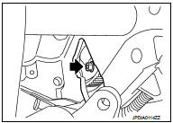
CAUTION:• Check fitting of dowel pin (
 )
when installing transaxle assembly to engine assembly.
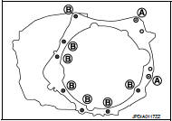
• When installing transaxle assembly to the engine assembly, attach the fixing bolts in accordance with the following.

• Set and screw in the drive plate location guide (commercial service tool: 31197CA000) (A) onto the stud bolts for the torque converter locate.
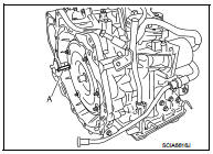
• When not using drive plate location guide, rotate torque converter so that the stud bolt (A) for mounting the drive plate location guide of torque converter aligns with the mounting position of starter motor.
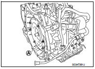
• Rotate crankshaft so that the hole (A) for inserting drive plate location guide of drive plate aligns with the mounting position (B) of starter motor.
NOTE:
When not using drive plate location guide, insert stud bolt of torque converter into the hole of drive plate, aligning the drive plate hole position and torque converter.
Note that the stud bolt strikes the drive plate hole position is not aligned the torque converter stud bolt.

• Align the position of tightening nuts (
) for drive plate with those of the torque converter, and temporarily tighten the nuts. Then, tighten the bolts with the specified torque.
:51 N·m
CAUTION:• When turning crankshaft, turn it clockwise as viewed from the front of the engine. • When tightening the tightening nuts for the torque converter after fixing the crankshaft pulley bolts, confirm the tightening torque of the crankshaft pulley mounting bolts. Refer to .
• After converter is installed to drive plate, rotate crankshaft several turns and check that transaxle rotates freely without binding.
Inspection and Adjustment
INSPECTION BEFORE INSTALLATION
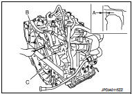
After inserting a torque converter to the CVT, check dimension (A) with in the reference value limit.
B : Scale
C : Straightedge
Dimension (A) : Refer to TM-308, "Torque Converter".
INSPECTION AFTER INSTALLATION
Check the following.
• Check for CVT fluid leakage and check CVT fluid level. Refer to TM-184, "Inspection". • Check CVT position. Refer to TM-194, "Inspection and Adjustment".• Start and warm up the engine. Visually check that there is no leakage of engine coolant and CVT fluid.
ADJUSTMENT AFTER INSTALLATION
When replacing the transaxle assembly, • Erase CVT fluid degradation level data. Refer to TM-159, "CONSULT-III Function (TRANSMISSION)".• Erase EEP ROM in TCM. Refer to TM-180, "Description".