Fluid cooler system
Exploded View
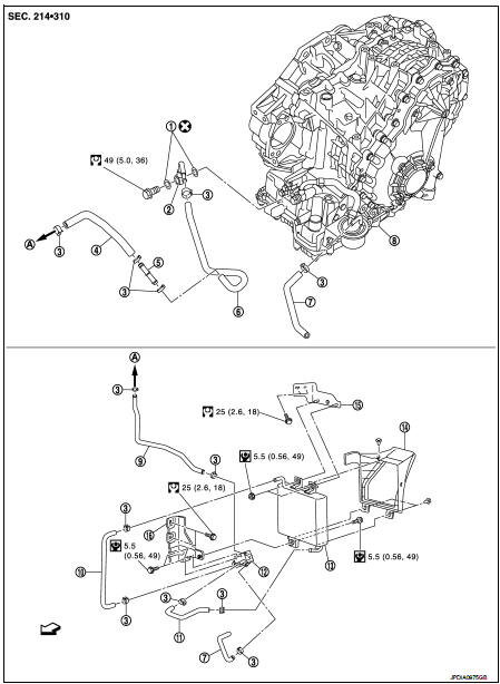
1. Copper washer
2. CVT fluid cooler tube 3. Hose clamp
4. Fluid cooler hose A
5. Fluid cooler tube
6. Fluid cooler hose B
7. Fluid cooler hose C
8. Transaxle assembly
9. Fluid cooler hose D
10. Fluid cooler hose E 11. Fluid cooler hose F 12. Bypass valve
13. Fluid cooler
14. Air guide
15. Bracket A
16. Bracket B
A. To radiator
 : Vehicle side
Removal and Installation
REMOVAL
1. Remove engine under cover. 2. Remove front bumper assembly. Refer to EXT-13, "Removal and Installation". 3. Remove air guide from fluid cooler. 4. Remove fluid cooler hose E and fluid cooler hose F. 5. Remove fluid cooler. 6. Remove air duct (inlet). Refer to EM-26, "Removal and Installation". 7. Remove fluid cooler hose C and fluid cooler hose D. 8. Remove bypass valve from bracket B. 9. Remove fluid cooler hose A and fluid cooler hose B. 10. Remove fluid cooler tube. 11. Remove bracket A and bracket B.12. Remove CVT fluid cooler tube from transaxle assembly.
INSTALLATION
Note the following, and install in the reverse order of removal.
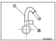
CAUTION:Never reuse copper washer. • When installing CVT fluid cooler tube (1) to transaxle assembly: - Contact CVT fluid cooler tube a boss portion (A) of the transaxle case.
- Tighten the bolt of CVT fluid cooler tube without moving the CVT fluid cooler tube
• Refer to the followings when installing fluid cooler hose.
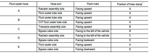

*: Refer to the illustrations for the specific position each hose clamp tab.
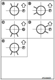
- The illustrations indicate the view from the hose ends.
F : Vehicle upper  G : Vehicle front
- When installing hose clamps center line of each hose clamp tab should be positioned as shown in the figure.
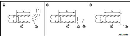
- Insert fluid cooler hose according to dimension (L) described below.

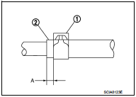
- Set hose clamps (1) at the both ends of fluid cooler hose (2) with dimension (A) from the hose edge.

- Hose clamp should not interfere with the bulge of fluid cooler tube.
Inspection
INSPECTION AFTER INSTALLATION
Check for CVT fluid leakage and CVT fluid level. Refer to TM-184, "Inspection".