B2614 Bcm
DTC DETECTION LOGIC
| DTC No. | CONSULT screen items (Trouble diagnosis content) | DTC Detection Condition | |
|---|---|---|---|
| B2614 | BCM (Body control module) |
Diagnosis condition | Always |
| Signal (terminal) | Accessory relay-1 control | ||
| Threshold | The following states are compared, and they do not match for 1 second or more:
|
||
| Diagnosis delay time | 1 second or more. | ||
POSSIBLE CAUSE
Harness or connectors (Accessory relay-1 control signal circuit is open or shorted)
BCM
Accessory relay-1
FAIL-SAFE
—
PERFORM DTC CONFIRMATION PROCEDURE
 CONSULT
Ignition switch ACC, and wait for 1 second or more.
Select “Self Diagnostic Result” mode of “BCM”.
Check DTC.
Is DTC detected?
YES>>Refer to DTC Diagnosis Procedure.
NO>>To check malfunction symptom before repair: Refer to Intermittent Incident.
NO>>Confirmation after repair: Inspection End.
CHECK ACCESSORY RELAY-1 CONTROL SIGNAL
Check voltage between BCM harness connector and ground.
| (+) | (–) | Condition | Voltage (Approx.) | ||
|---|---|---|---|---|---|
| BCM | |||||
| Connector | Terminal | ||||
| M80 | 113 | Ground | Ignition switch | OFF | 0 – 0.5 V |
| ACC or ON | Battery voltage | ||||
Is the inspection result normal?
YES>>Replace BCM. Refer to Removal and Installation.
NO>>GO TO 2.
CHECK ACCESSORY RELAY-1 CONTROL SIGNAL CIRCUIT
Ignition switch OFF.
Disconnect BCM connector and accessory relay-1 connector.
Check continuity between BCM harness connector and accessory relay-1 harness connector.
BCM Accessory relay-1 Continuity Connector Terminal Connector Terminal M80 113 J-3 2 Yes Check continuity between BCM harness connector and ground.
BCM — Continuity Connector Terminal M80 113 Ground No
Is the inspection result normal?
YES>>GO TO 3.
NO>>Repair or replace harness or connectors.
CHECK ACCESSORY RELAY-1 GROUND CIRCUIT
Check continuity between accessory relay-1 harness connector and ground.
| Accessory relay-1 | — | Continuity | |
| Connector | Terminal | ||
| J-3 | 1 | Ground | Yes |
Is the inspection result normal?
YES>>GO TO 4.
NO>>Repair or replace harness or connectors.
CHECK ACCESSORY RELAY-1
Refer to Component Inspection.
Is the inspection result normal?
YES>>Replace BCM. Refer to Removal and Installation.
NO>>Replace accessory relay-1.
CHECK ACCESSORY RELAY-1
Ignition switch OFF.
Disconnect accessory relay-1 connector.
Check the continuity between accessory relay-1 terminals.
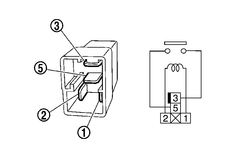
Accessory relay-1 Condition Continuity Terminals 3 5 12 V direct current supply between terminals 1 and 2 Yes No current supply No
Is the inspection result normal?
YES>>Inspection End.
NO>>Replace accessory relay-1.