Brake Master Cylinder
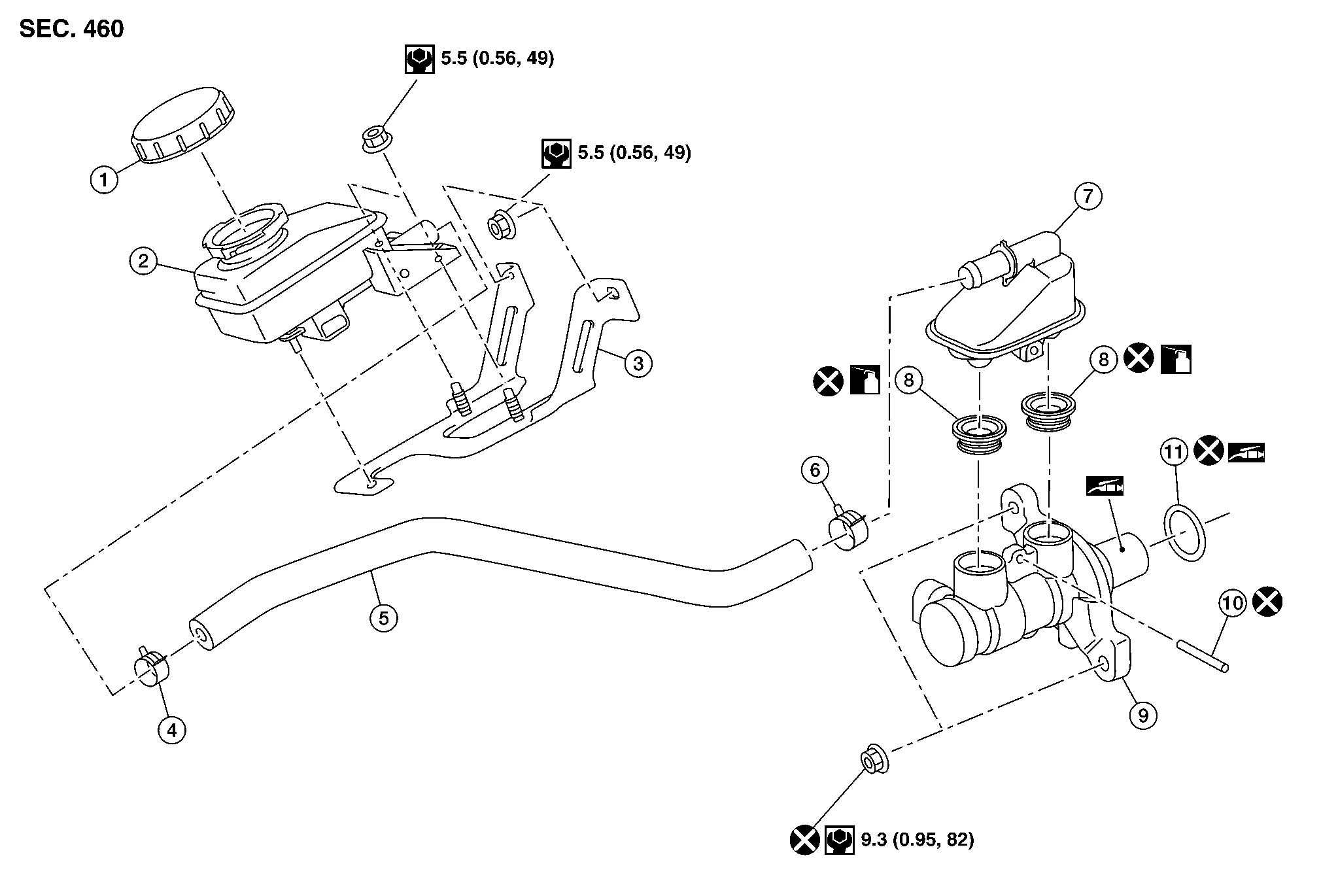
| 1. | Sub tank cap | 2. | Sub tank | 3. | Sub tank bracket |
| 4. | Clamp | 5. | Hose | 6. | Clamp |
| 7. | Reservoir tank | 8. | Grommet | 9. | Cylinder body |
| 10. | Pin | 11. | O-ring | ||
 |
Apply PBC (Poly Butyl Cuprysil) grease or silicone-based grease. | ||||
 |
Apply brake fluid. | ||||
REMOVAL
Remove sub tank cap.
Remove the sub tank bracket nuts (A), release the brake fluid level switch harness clips (B) and position the sub tank assembly (1) aside.
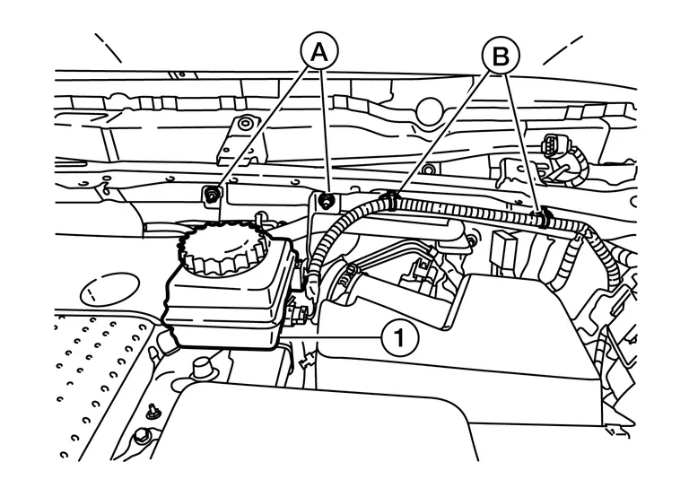
Remove air cleaner case as an assembly. Refer to Removal and Installation.
Disconnect the brake pipes from the master cylinder assembly with a flare nut wrench.
Remove the master cylinder assembly.
INSTALLATION
Installation is in the reverse order of removal.
Do not reuse master cylinder assembly nuts.
Do not reuse O-ring.
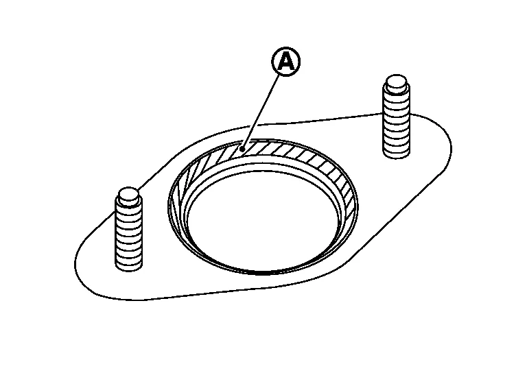
Apply PBC (Poly Butyl Cuprysil) silicone-based grease to the brake booster (A) when installing the master cylinder assembly to the brake booster.
Temporarily tighten the brake tube flare nut to the master cylinder assembly by hand. Then tighten it to the specified torque with a flare nut crowfoot and torque wrench. Refer to Exploded View.
After installation, perform the air bleeding. Refer to Bleeding Brake System.
DISASSEMBLY
Secure the master cylinder assembly in a vise.
Remove the reservoir tank pin using suitable tools.
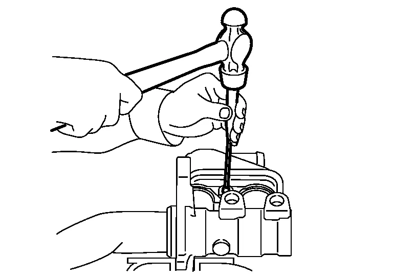
Remove the reservoir tank and grommets from the cylinder body. Discard the grommets.
ASSEMBLY
Apply new brake fluid to the grommets and install them to the cylinder body.
Install the reservoir tank to the cylinder body.
Tilt the reservoir tank so that the pin can be inserted. Insert a pin using suitable tools.