Rear
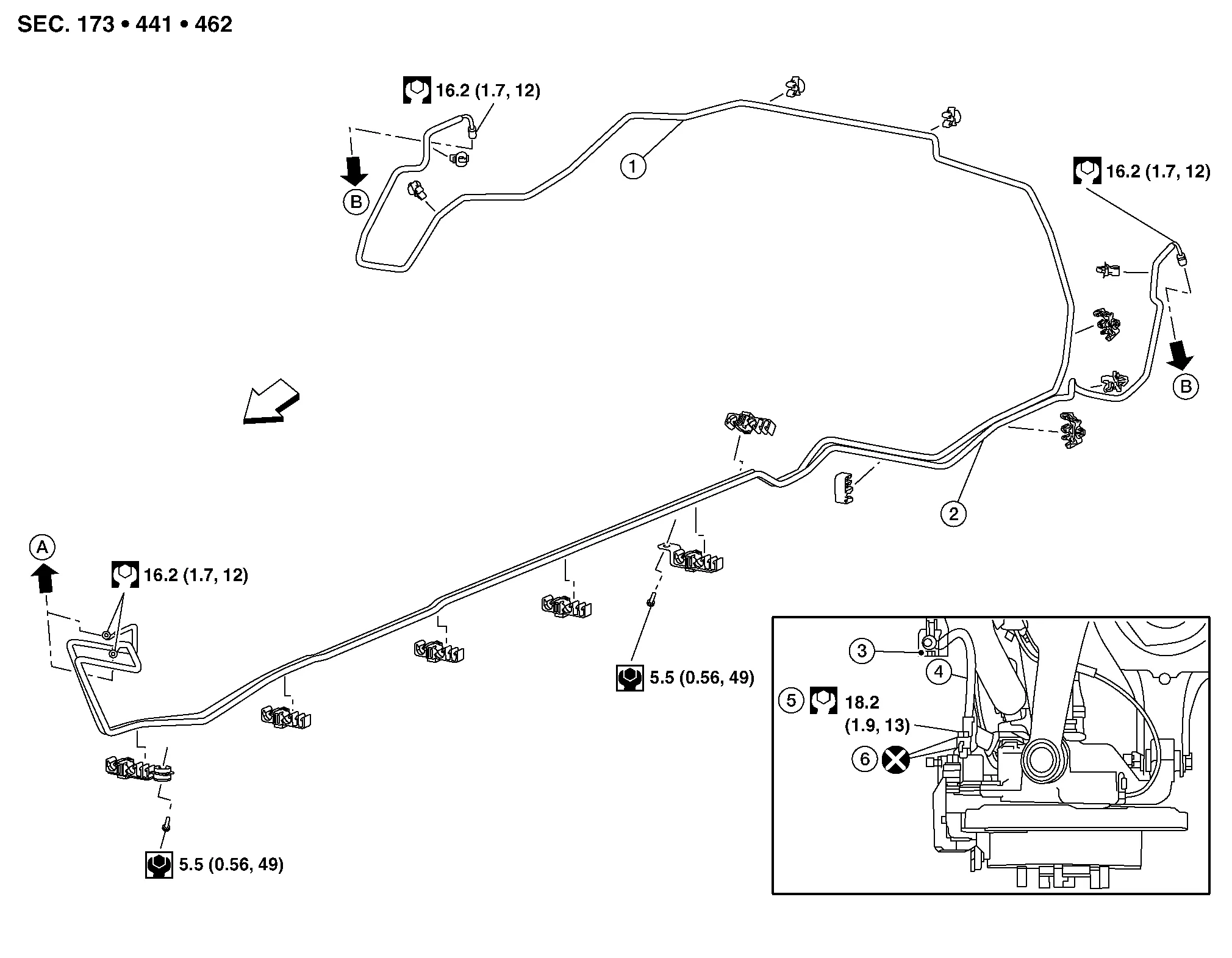
| 1. | Rear brake pipe assembly - RH | 2. | Rear brake pipe assembly - LH | 3. | Lock plate |
| 4. | Rear brake hose | 5. | Union bolt | 6. | Copper sealing washers |
| A. | To brake pipe connector. Refer to Exploded View. | B. | To rear brake hose |  |
Front |
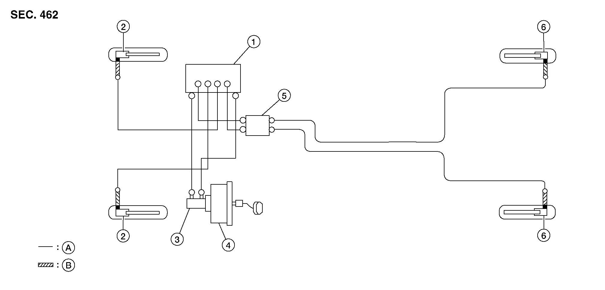
| 1. | ABS actuator and electric unit (control unit) | 2. | Front disc brake | 3. | Master cylinder assembly |
| 4. | Brake booster | 5. | Connector | 6. | Rear disc brake |
| A. | Brake tube | B. | Brake hose | ||
 : Flare nut |
|||||
 : Union bolt |
|||||
REMOVAL
Remove sub tank cap.
Remove wheels and tires using power tool.
Loosen the flare nut with a flare nut wrench and separate the brake tube from the hose.
Remove the union bolt (A) and the brake hose from the brake caliper. Remove and discard the copper sealing washers (1).

Remove the lock plate and remove the brake hose.
INSTALLATION
Assemble the union bolt (A) and the copper sealing washers (1) to the brake hose and install it as an assembly to the brake caliper. Align the brake hose L-pin by aligning it with the brake caliper hole, and tighten the union bolt (1) to the specified torque.
Install the brake pipe to the brake hose, temporarily tighten the flare nut by hand until it does not rotate further, and attach the brake hose to the bracket with the lock plate.
Tighten the flare nut to the specified torque with a flare nut crowfoot and a torque wrench.
Refill with new brake fluid and perform the air bleeding. Refer to Bleeding Brake System.
Install the wheels and tires. Refer to Removal and Installation.
Perform inspection after installation. Refer to Inspection.