Body Interior
Exit Assist Function
In this manual: Body Interior
3steps
~18min
2/5difficulty
Done 0 of 3
SYSTEM DIAGRAM
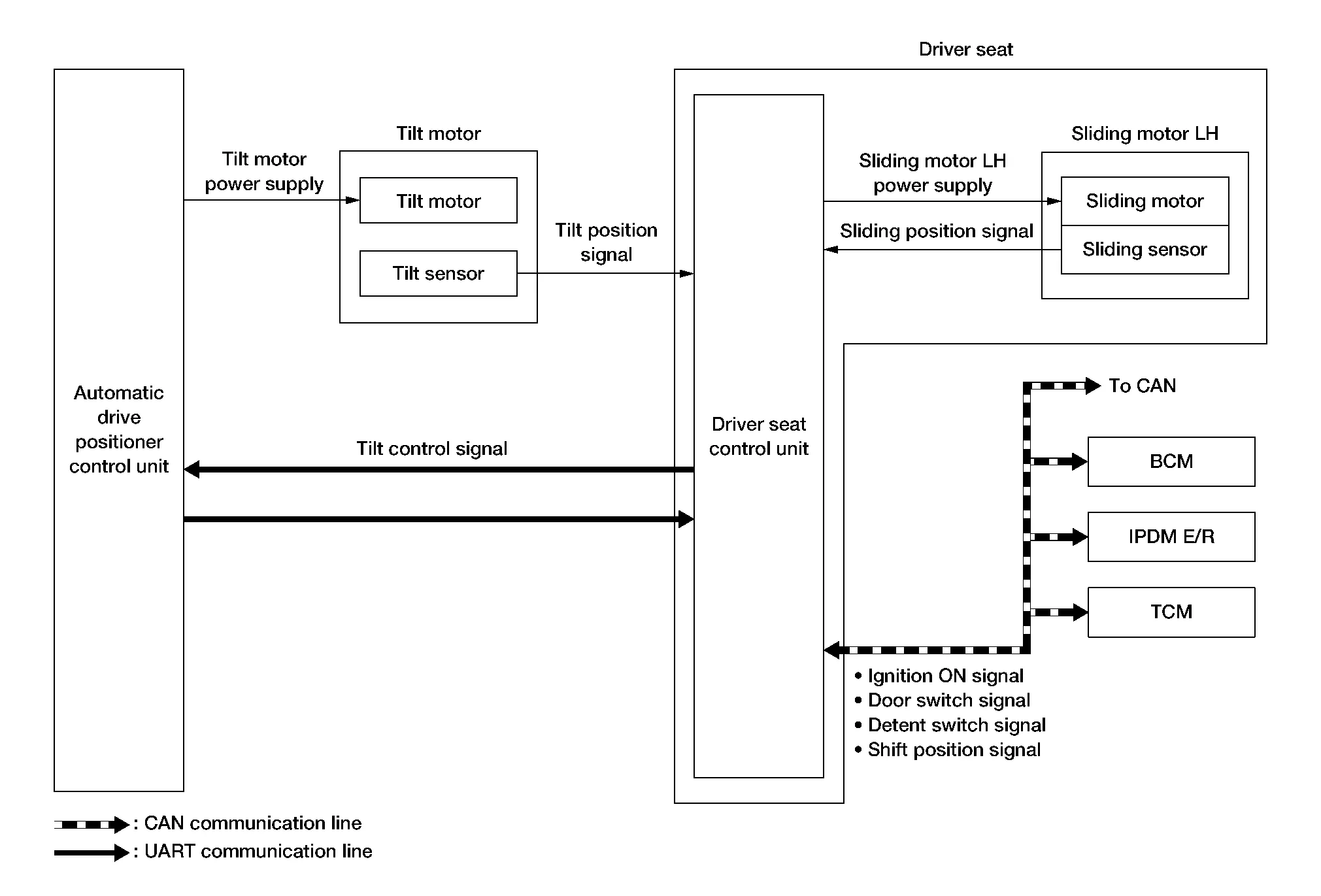
SIGNAL TRANSMISSION FUNCTION LIST
Several types of signals are transmitted from the following units to the driver seat control unit via CAN communication.
| Component | Signal |
|---|---|
| BCM |
|
| TCM | Shift position signal |
| IPDM E/R | Detention switch signal |
DESCRIPTION
When exiting, if the conditions are satisfied, the seat is moved backward from normal sitting position and the steering column is moved up.
The seat slide amount at entry/exit operation can be changed.
Operation Procedure
Shift position P position.
Open the front door LH with ignition switch OFF.
Front seat LH and steering column will move to the exiting position.
Operation Condition
Satisfy all of the following items. The exit assist function is not performed if these items are not satisfied.
| Item | Request status |
|---|---|
| Ignition switch | OFF |
| System setting [Entry/exit assist function] | ON |
| Initialization | Done |
Switch inputs
|
OFF (Not operated) |
| CVT selector lever | P position |
Detail Flow
| Order | Input | Output | Control unit condition |
|---|---|---|---|
| 1 | Front door switch LH | — | Driver seat control unit receives front door switch LH signal (open) from BCM via CAN communication. |
| 2 | — | Motors (seat sliding LH, tilt) | Driver seat control unit operates the seat sliding motor LH, which recognizes that the driver side door is opened with ignition switch OFF. Driver seat control unit then requests the operations of tilt motor to automatic drive positioner control unit via UART communication. The automatic drive positioner control unit operates each motor for a constant amount. |
Was this page helpful?