Front Bumper
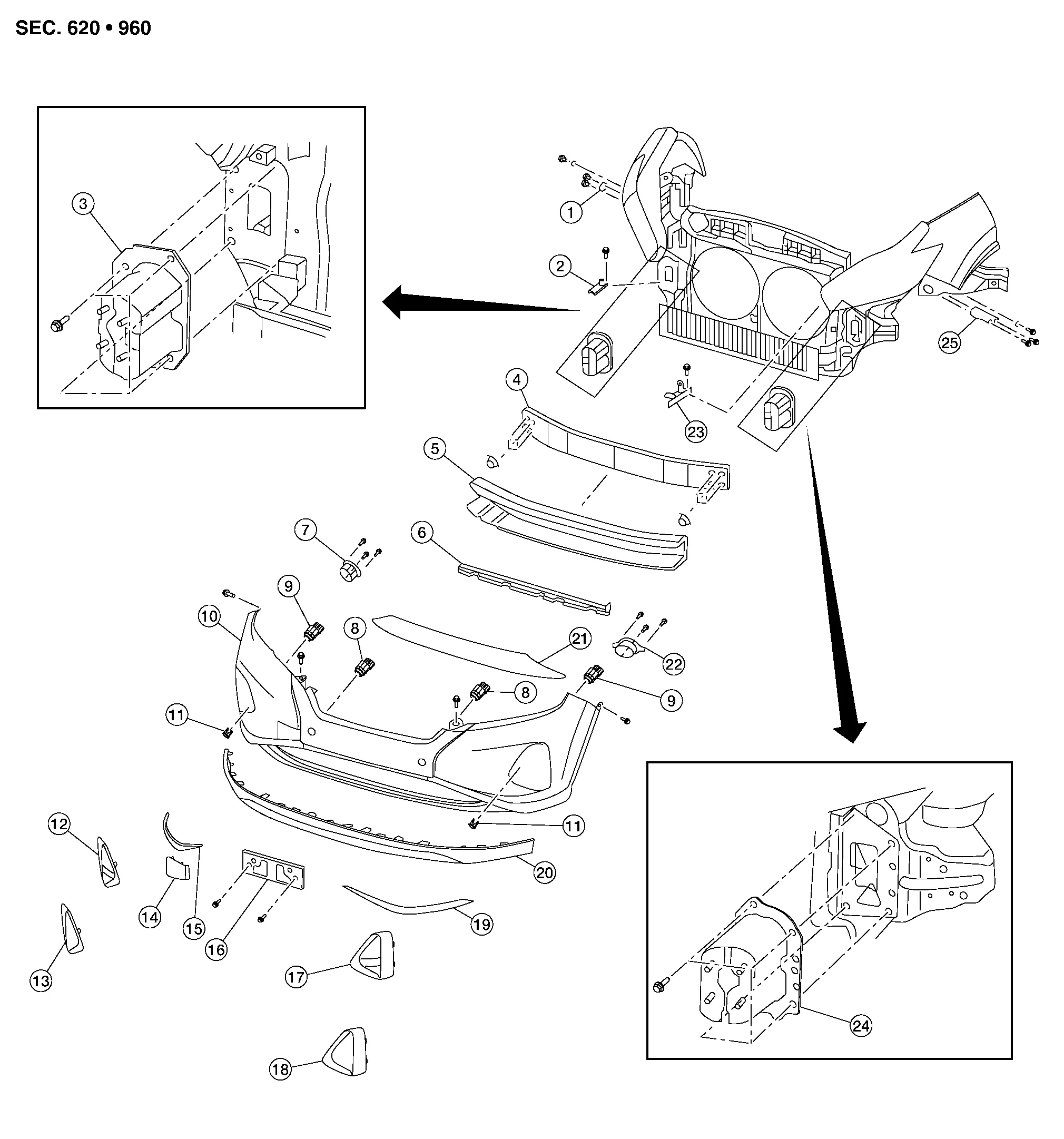
| 1. | Front bumper fascia side bracket (RH) | 2. | Front bumper side retainer (RH) | 3. | Front bumper reinforcement bracket (RH) |
| 4. | Front bumper reinforcement | 5. | Front energy absorber | 6. | Front bumper air guide |
| 7. | Front fog lamp (RH) (if equipped) | 8. | Sonar sensor (inner) | 9. | Sonar sensor (outer) |
| 10. | Front bumper fascia | 11. | Sonar finisher | 12. | Front fog lamp finisher (RH) (if equipped) |
| 13. | Front bumper fascia finisher (RH) (without fog lamp) | 14. | Tow cover | 15. | Front bumper fascia molding (RH) |
| 16. | Front license plate bracket | 17. | Front fog lamp finisher (LH) (if equipped) | 18. | Front bumper fascia finisher (LH) (without fog lamp) |
| 19. | Front bumper fascia molding (LH) | 20. | Front spoiler | 21. | Front bumper lower grille |
| 22. | Front fog lamp (LH) (if equipped) | 23. | Front bumper side retainer (LH) | 24. | Front bumper reinforcement bracket (LH) |
| 25. | Front bumper fascia side bracket (LH) |
REMOVAL
Remove the front grille. Refer to Removal and Installation.
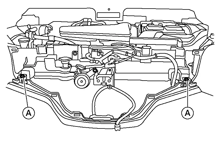
Remove the front bumper fascia clips (A).
Partially remove front over fender (LH/RH). Refer to Exploded View.
Remove engine side cover. Refer to Exploded View.
Partially remove front fender protector (LH/RH). Refer to Exploded View.
Remove front undercover (front half). Refer to Exploded View.
Remove the front bumper fascia screws (A) (LH/RH).
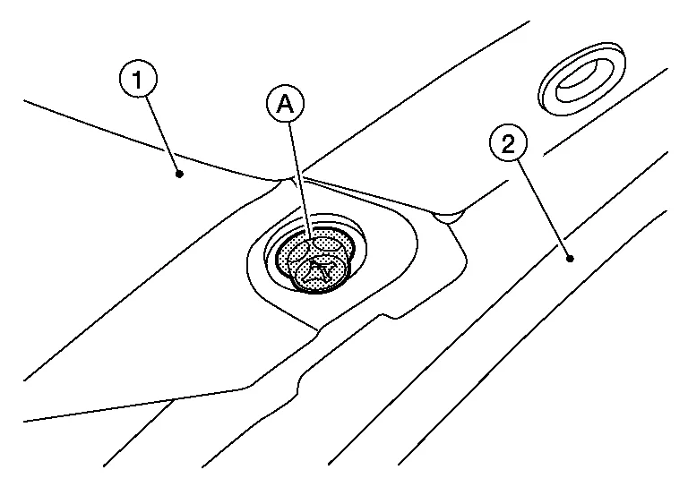
(1): Front bumper fascia
(2): Front over fender
Disconnect fog lamp harness connector (LH/RH) (if equipped).
Disconnect sonar sensor harness connectors.
Release front bumper fascia pawls from front bumper fascia side bracket (LH/RH) and remove.
Remove the front energy absorber.
Remove front bumper reinforcement nuts and front bumper reinforcement.
Remove front bumper reinforcement support bolts and front bumper reinforcement support (LH/RH).
Remove front bumper side bracket bolts and the front bumper side bracket (LH/RH) (if necessary).
INSTALLATION
Installation is in the reverse order of removal.
Intelligent Cruise Control (ICC): Refer to Description.
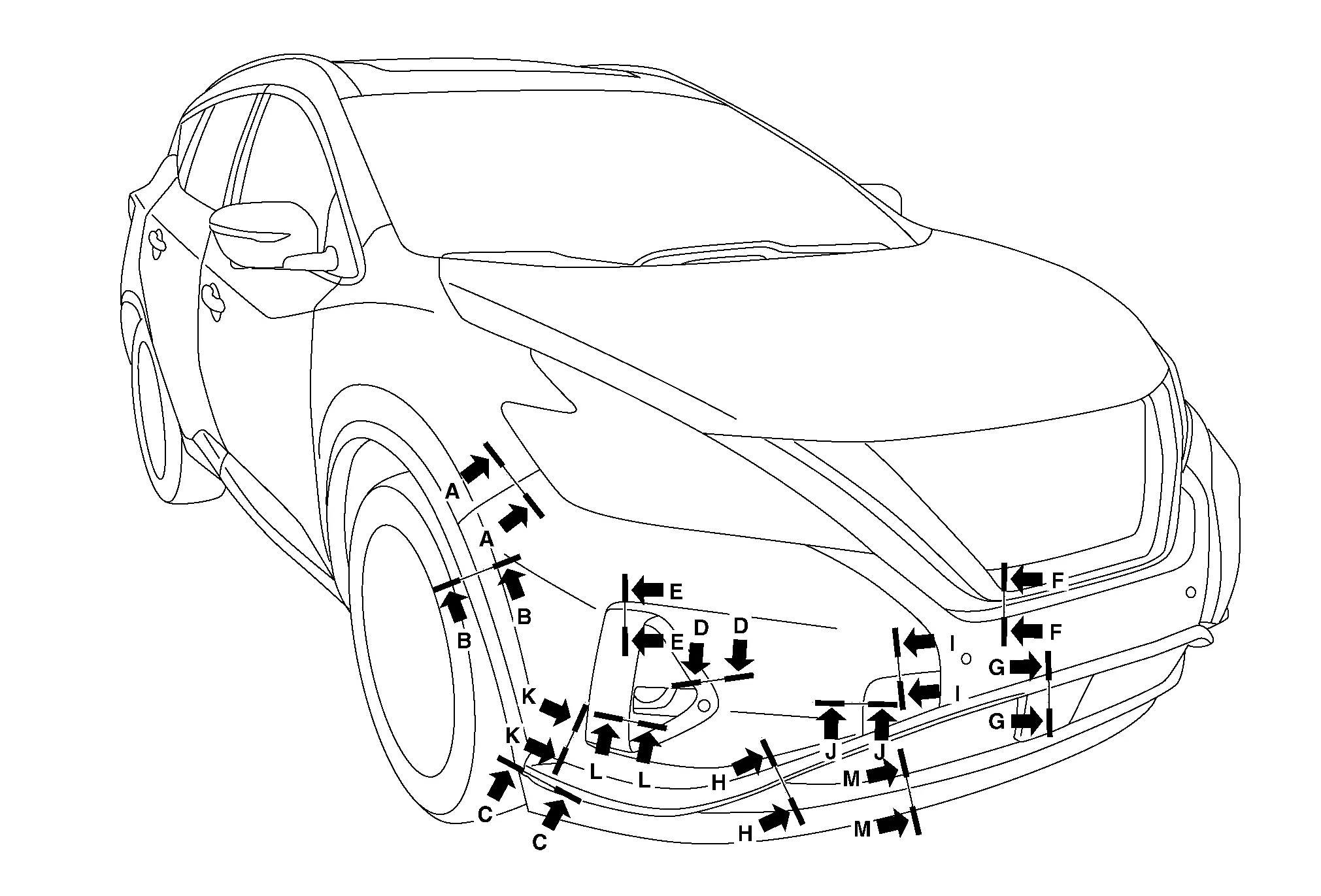
| Section | Measurement | Minimum | Target Value | Maximum |
|---|---|---|---|---|
| A-A | Clearance | 0.0 (0.00) | 0.3 (0.01) | 1.0 (0.04) |
| Surface height | -0.1 (0.00) | 0.7 (0.03) | 1.5 (0.06) | |
| B-B | Clearance | 0.0 (0.00) | 0.5 (0.02) | 1.4 (0.06) |
| C-C | Clearance | 0.0 (0.00) | 0.8 (0.03) | 1.7 (0.07) |
| Surface height | -0.1 (0.00) | 0.0 (0.00) | 1.0 (0.04) | |
| D-D | Clearance | 0.0 (0.00) | 1.0 (0.04) | 2.0 (0.08) |
| E-E | Clearance | 0.0 (0.00) | 1.0 (0.04) | 2.0 (0.08) |
| F-F | Clearance | 0.2 (0.01) | 1.5 (0.06) | 2.8 (0.11) |
| G-G | Clearance | 0.4 (0.02) | 1.4 (0.06) | 2.4 (0.09) |
| H-H | Clearance | 0.5 (0.02) | 1.5 (0.06) | 2.5 (0.10) |
| I-I | Clearance | 0.0 (0.00) | 0.5 (0.02) | 1.0 (0.04) |
| Surface height | -0.2 (-0.01) | 0.3 (0.01) | 0.8 (0.03) | |
| J-J | Clearance | 0.0 (0.00) | 0.5 (0.02) | 1.0 (0.04) |
| Surface height | -0.2 (-0.01) | 0.3 (0.01) | 0.8 (0.03) | |
| K-K | Clearance | 0.0 (0.00) | 1.0 (0.04) | 2.0 (0.08) |
| L-L | Clearance | 0.3 (0.01) | 2.1 (0.08) | 3.9 (0.15) |
| M-M | Clearance | 0.0 (0.00) | 0.3 (0.01) | 1.3 (0.05) |