Precaution. Precautions
The Supplemental Restraint System such as “AIR BAG” and “SEAT BELT PRE-TENSIONER”, used along with a front seat belt, helps to reduce the risk or severity of injury to the driver and front passenger for certain types of collisions.
Information necessary to service the system safely is included in the “SRS AIR BAG” and “SEAT BELT” sections of this Service Manual.
To avoid rendering the SRS inoperative, which could increase the risk of personal injury or death in the event of a collision that would result in air bag inflation, it is recommended that all maintenance and repair be performed by an authorized NISSAN/INFINITI dealer.
Improper repair, including incorrect removal and installation of the SRS, can lead to personal injury caused by unintentional activation of the system. For removal of Spiral Cable and Air Bag Module, see “SRS AIR BAG”.
Never use electrical test equipment on any circuit related to the SRS unless instructed to in this Service Manual. SRS wiring harnesses can be identified by yellow and/or orange harnesses or harness connectors.
PRECAUTIONS WHEN USING POWER TOOLS (AIR OR ELECTRIC) AND HAMMERS
When working near the Air Bag Diagnosis Sensor Unit or other Air Bag System sensors with the ignition/power switch ON or engine running, never use air or electric power tools or strike near the sensor(s) with a hammer. Heavy vibration could activate the sensor(s) and deploy the air bag(s), possibly causing serious injury.
When using air or electric power tools or hammers, always switch the ignition/power switch OFF, disconnect the 12V battery or batteries, and wait at least 3 minutes before performing any service.
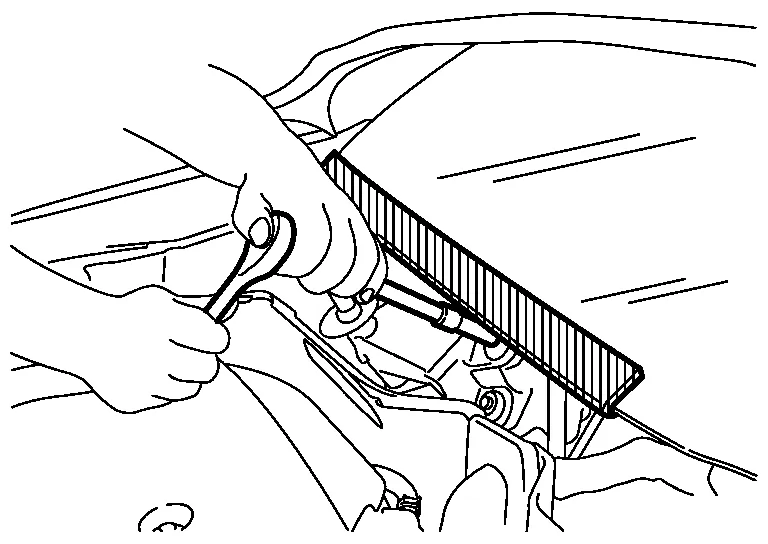
When performing the procedure after removing cowl top cover, cover the lower end of windshield with urethane, etc to prevent damage to windshield.
Turn ignition switch OFF and disconnect the battery cable from the negative terminal before connecting or disconnecting the CVT assembly harness connector. Because battery voltage is applied to TCM even if ignition switch is turned OFF.

When connecting or disconnecting pin connectors into or from TCM, do not damage pin terminals (bend or break).

Check that there are not any bends or breaks on TCM pin terminal, when connecting pin connectors.
Perform TCM input/output signal inspection and check whether TCM functions normally or not before replacing TCM. Refer to Reference Value.

Perform “DTC (Diagnostic Trouble Code) CONFIRMATION PROCEDURE”.
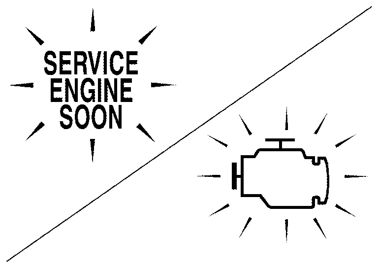
If the repair is completed DTC should not be displayed in the “DTC CONFIRMATION PROCEDURE”.
Always use the specified brand of CVT fluid. Refer to Fluids and Lubricants.
Use lint-free paper not cloth rags during work.
Dispose of the waste oil using the methods prescribed by law, ordinance, etc. after replacing the CVT fluid.
The TCM and ECM have an on board diagnostic system. It will light up the malfunction indicator lamp (MIL) to warn the driver of a malfunction causing emission deterioration.
REMOVAL
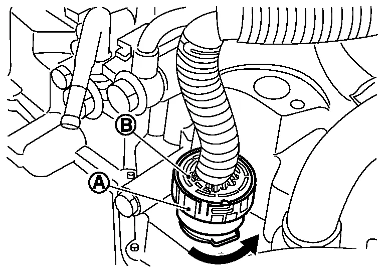
Rotate bayonet ring (1) counterclockwise. Pull out CVT unit harness connector (2) upward and remove it.
INSTALLATION
Align marking (A) on CVT unit harness connector terminal with marking (B) on bayonet ring. Insert CVT unit harness connector.
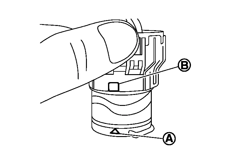
Rotate bayonet ring clockwise.
Rotate bayonet ring clockwise until marking (A) on CVT unit harness connector terminal body is aligned with the slit (B) on bayonet ring as shown in the figure (correctly fitting condition).
