Preliminary information
ESTABLISHING COMMUNICATION BETWEEN XR25 TOOL AND ECU
Connect the XR25 tool to the diagnostic socket.
Set the selector to S8
Switch on the ignition.
Press D13

IDENTIFYING THE ECU
Identifying the ECU does not involve reading a fault code, but reading the ECU's MPR number directly, after communication has been established with the ECU.
PRESS G70*
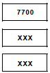
The MPR number is then shown on the central display in three sequences.
Each sequence stays on screen for about two seconds. The display is repeated twice.
MEMORY CLEARING (ignition on)
After work on the injection system, the ECU memory can be cleared using code G0**.
If the information obtained with the XR25 tool requires checking electrical continuity, connect terminal block Sus. 1228.
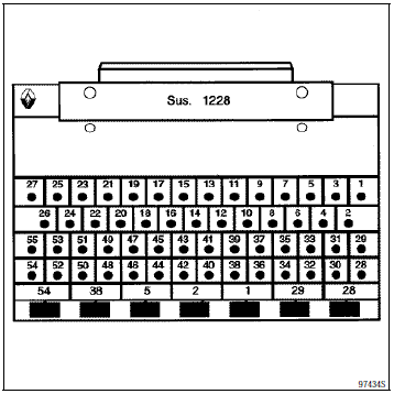
Terminal block Sus. 1228 consists of a 55-way socket attached to a printed circuit board with 55 copper pads, numbered 1 to 55.
Using the wiring diagrams, you can easily identify the wires connecting the component(s) to be checked.
IMPORTANT:
All checks using terminal block Sus. 1228 must be carried out with the battery disconnected.
The terminal block is designed for use with an ohmmeter only. Never apply 12 volts to the test points.
DESCRIPTION OF DIAGNOSTIC STEPS
The sequence described below must be followed for every fault.
XR25 FAULT CHECK
This step is the essential starting point before any work on the vehicle.
Several constraints apply when handling the bar graphs:
A priority order when several bar graphs are lit.
How to interpret a bar graph depending on whether it is lit steadily or flashing.
1 - Order of priority
A group of lit bar graphs corresponding to sensors sharing the same 12 V supply or the same ground indicates a fault in that supply. These priorities are covered in the "INSTRUCTIONS" section of the relevant bar graph diagnosis.
2 - Input/output fault bar graphs
a) Lit steadily:
The fault is present: treat the fault following the procedure given in the chapter "INTERPRETATION OF XR25 BAR GRAPHS".
b) Flashing:
Note the bar graphs displayed on the scan tool.
Clear the ECU memory and try to light the bar graph again: with ignition on, at idle (or at starter speed), or by a road test (the "INSTRUCTIONS" section in the diagnosis of the relevant bar graph can help you find the conditions for lighting the bar graph).
If the bar graph has lit again (steady or flashing):
The fault is present again. In this case, treat the fault bar graph.
If the bar graph has not lit again, check:
the electrical circuits corresponding to the flashing fault,
the connectors of these circuits (corrosion, bent pins...),
the resistance of the detected faulty component,
the condition of the wiring (melted or cut insulation, chafing...).
NOTE: If the customer symptom does not match the flashing fault bar graph (example: flashing air temperature sensor fault bar graph but no customer symptom), disregard this stored fault and erase it.
3 - No bar graphs displayed
If no fault bar graph is lit on the XR25 tool, a check of states and parameters should be carried out. This can help you locate the problem.
XR25 CHECK OF STATES AND PARAMETERS
The purpose of the states and parameters check is to verify the states and parameters that do not light a fault bar graph when they are out of tolerance. This step therefore allows:
To diagnose faults with no fault bar graph lit that may correspond to a customer complaint (example: missing Accelerator Released information causing unstable idle).
To verify correct operation of the injection system and make sure a fault will not reappear shortly after repair.
This chapter therefore contains a diagnosis of states and parameters, under the conditions of their check (example: diagnosis of # 01 with ignition on and diagnosis of # 01 with engine running).
If a state does not operate normally or a parameter is out of tolerance, consult the diagnosis page indicated in the "Diagnosis" column.
XR25 CHECK CORRECT
If the XR25 check is correct but the customer complaint is still present, treat the problem by customer symptom.
Treatment of customer symptom
This chapter provides fault-location trees giving a series of possible causes for the problem.
These lines of investigation should only be used in the following case:
No fault bar graph appears on the XR25 tool.
No fault is detected during the states and parameters check.
The vehicle does not operate correctly.
CHECK AFTER REPAIR
This operation is a simple verification of the repair (by a command, by an XR25 command mode, ...).
It checks that the system on which the work was carried out is electrically correct.
It is a preliminary step before the road test.
ROAD TEST CHECK
A road test is essential to guarantee correct operation of the vehicle and to test the quality of the repair. Its purpose is to verify that no fault occurs (or will occur) while driving.
To be meaningful, the road test must be carried out under specific driving conditions.
Driving conditions for adaptive learning:
During the road test, hold the engine speed steady for a few moments between:
220 < # 01 < 340 mbar
then 340 < # 01 < 470 mbar
then 470 < # 01 < 600 mbar
then 600 < # 01 < 730 mbar
then 730 < # 01 < 870 mbar
Do not exceed an engine speed of 4800 rpm.
The engine must be warm (coolant temperature > 75 °C).
For this test, it is advised to start at a fairly low engine speed, in 3rd or 4th gear, with very gradual acceleration so as to hold the desired pressure for 10 seconds in each zone.
The test must then be continued by driving normally, smoothly and varied, over a distance of 5 to 10 km.
Test yourself
A quick Renault Kangoo quiz: every answer comes with an explanation and a link to the manual page.