Automatic Running Board Switch
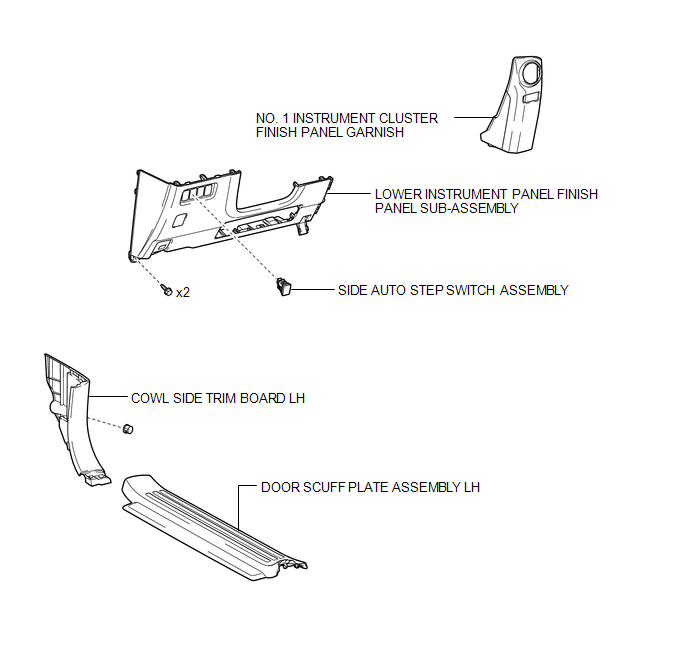
Removal REMOVAL PROCEDURE
1. REMOVE DOOR SCUFF PLATE ASSEMBLY LH

2. REMOVE COWL SIDE TRIM BOARD LH
3. REMOVE NO. 1 INSTRUMENT CLUSTER FINISH PANEL GARNISH
4. REMOVE LOWER INSTRUMENT PANEL FINISH PANEL SUB-ASSEMBLY
5. REMOVE SIDE AUTO STEP SWITCH ASSEMBLY
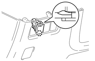
(a) Disengage the 2 claws and remove the side auto step switch assembly. |
 |
1. INSPECT SIDE AUTO STEP SWITCH ASSEMBLY
(a) Measure the resistance according to the value(s) in the table below. Standard Resistance:
|
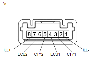 |
(b) Apply battery voltage to the connector and check the LED illumination.
OK:
Measurement Condition | Specified Condition |
|---|---|
Battery positive (+) → Terminal 7 (ILL+) Battery negative (-) → Terminal 2 (ILL-) |
LED illuminates |
HINT:
A bolt without a torque specification is shown in the standard bolt chart (See page  ).
PROCEDURE
1. INSTALL SIDE AUTO STEP SWITCH ASSEMBLY
(a) Engage the 2 claws and install the side auto step switch assembly.
2. INSTALL LOWER INSTRUMENT PANEL FINISH PANEL SUB-ASSEMBLY
3. INSTALL NO. 1 INSTRUMENT CLUSTER FINISH PANEL GARNISH
4. INSTALL COWL SIDE TRIM BOARD LH
5. INSTALL DOOR SCUFF PLATE ASSEMBLY LH
Test yourself
A quick Toyota 4Runner quiz: every answer comes with an explanation and a link to the manual page.