Terminals Of Ecu
1. CHECK 4WD CONTROL ECU
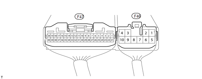
(a) Measure the voltage and resistance according to the value(s) in the table below.
Terminal No. (Symbol) | Wiring Color | Terminal Description | Condition | Specified Condition |
|---|---|---|---|---|
F47-2 (4WDL) - F46-4 (GND) |
L - W-B |
Transfer indicator switch (L4 position) |
Ignition switch ON Transfer shift lever position H2 or H4 |
10.5 to 14 V |
Ignition switch ON Transfer shift lever position L4 or N |
Below 1.5 V |
|||
F47-3 (4WD) - F46-4 (GND) |
B - W-B |
Transfer indicator switch (4WD position) |
Ignition switch ON Transfer shift lever position H2 |
10.5 to 14 V |
Ignition switch ON Transfer shift lever position H4, L4 or N |
Below 1.5 V |
|||
F47-9 (DL1) - F46-4 (GND) |
LG - W-B |
A.D.D. actuator limit switch |
Ignition switch ON Transfer shift lever position H2 |
Below 1.5 V |
Ignition switch ON Transfer shift lever position H4, L4 or N |
10.5 to 14 V |
|||
F47-10 (DL2) - F46-4 (GND) |
GR - W-B |
A.D.D. actuator limit switch |
Ignition switch ON Transfer shift lever position H2 |
10.5 to 14 V |
Ignition switch ON Transfer shift lever position H4, L4 or N |
Below 1.5 V |
|||
F47-15 (ADD) - F46-4 (GND) |
W - W-B |
A.D.D. detection switch |
Ignition switch ON Transfer shift lever position H2 |
9.5 to 14 V |
Ignition switch ON Transfer shift lever position H4, L4 or N |
Below 1.5 V |
|||
F47-16 (NP) - F46-4 (GND) |
R - W-B |
Transfer indicator switch (Neutral position) |
Ignition switch ON Transfer shift lever position N |
Below 1.5 V |
Ignition switch ON Transfer shift lever position not N |
10.5 to 14 V |
|||
F47-19 (CANH) - F46-4 (GND) |
G - W-B |
CAN communication line |
Ignition switch ON |
Pulse generation (See waveform 1) |
F47-20 (CANL) - F46-4 (GND) |
W - W-B |
CAN communication line |
Ignition switch ON |
Pulse generation (See waveform 2) |
F47-21 (L4) - F46-4 (GND) |
R - W-B |
Transfer L4 signal |
Ignition switch ON Transfer shift lever position H2 or H4 |
10 to 14 V |
Ignition switch ON Transfer shift lever position L4 or N |
Below 1.5 V |
|||
F46-1 (DM1) - F46-4 (GND) |
B - W-B |
A.D.D. actuator motor |
Ignition switch ON Transfer shift lever position H2 → H4, L4 or N (During operation of A.D.D. actuator motor from FREE to LOCK) |
10 to 14 V |
Ignition switch ON Transfer shift lever position H2 → H4, L4 or N (A.D.D. actuator motor stopped) |
Below 1.5 V |
|||
F46-3 (IG) - F46-4 (GND) |
R - W-B |
IG power |
Ignition switch ON |
11 to 14 V |
F46-4 (GND) - Body ground |
W-B - Body ground |
Ground |
Always |
Below 1 Ω |
F46-5 (DM2) - F46-4 (GND) |
Y - W-B |
A.D.D. actuator motor |
Ignition switch ON Transfer shift lever position H4, L4 or N → H2 (During operation of A.D.D. actuator motor from LOCK to FREE) |
10 to 14 V |
Ignition switch ON Transfer shift lever position H4, L4 or N → H2 (A.D.D. actuator motor stopped) |
Below 1.5 V |
(b) Using an oscilloscope, check waveform 1.
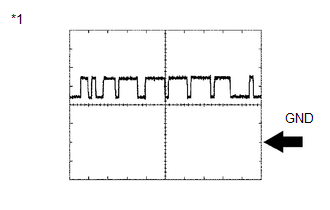 Waveform 1 (Reference)
Item | Content |
|---|---|
Terminal No. (Symbols) |
F47-19 (CANH) - F46-4 (GND) |
Tool setting |
1 V/DIV., 10 μsec./DIV. |
Condition |
Engine stopped and ignition switch ON |
*1 |
Waveform 1 |
HINT:
The waveform varies depending on the CAN communication signal.
(c) Using an oscilloscope, check waveform 2.
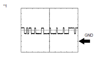 Waveform 2 (Reference)
Item | Content |
|---|---|
Terminal No. (Symbols) |
F47-20 (CANL) - F46-4 (GND) |
Tool setting |
1 V/DIV., 10 μsec./DIV. |
Condition |
Engine stopped and ignition switch ON |
*1 |
Waveform 2 |
HINT:
The waveform varies depending on the CAN communication signal.
Test yourself
A quick Toyota 4Runner quiz: every answer comes with an explanation and a link to the manual page.