Removal
REMOVAL
PRECAUTION / NOTICE / HINT
The procedures required (adjustment, calibration, initialization or registration) to be performed after parts have been removed, installed or replaced during steering wheel assembly removal/installation are shown below.
Procedure Required After Replacing / Removing / Installing PartsReplacement part or procedure | Necessary Procedures | Effects / Inoperative Function When Necessary Procedure Not Performed | Link |
|---|---|---|---|
Disconnect the cable from the negative (-) battery terminal. |
Initialize Back Door Lock |
Door Lock Control System |
 |
Memorize Steering Angle Neutral Point |
Lane Departure Alert System (with Steering Control) |
|
|
Pre-Collision System |
NOTICE:
- Do not replace the spiral cable sub-assembly with sensor while the battery is connected and the ignition switch is in the ON position.
- Do not swap the spiral cable sub-assembly with sensor without the steering wheel installed while the battery is connected and the ignition switch is in the ON position.
- Make sure the steering wheel assembly is installed and in the straight-ahead position when checking the steering angle sensor.
PROCEDURE
1. ALIGN FRONT WHEELS STRAIGHT AHEAD
2. REMOVE HORN BUTTON ASSEMBLY
Click here
3. REMOVE STEERING WHEEL ASSEMBLY
(a) Disconnect the 2 connectors from the clock spring sub-assembly with sensor. |
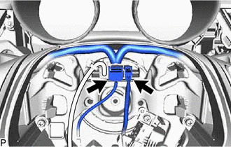 |
(b) With steering heater:
(1) Disconnect the steering heater connector. |
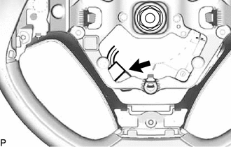 |
(c) Remove the steering wheel adjusting nut. |
|
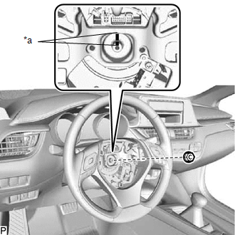
(d) Place alignment marks on the steering wheel assembly and the main steering shaft.
(e) Using the SST, remove the steering wheel assembly. SST: 09950-50013 09951-05010 09952-05010 09953-05020 09954-05031 NOTICE: Apply a small amount of grease to the threads and the end of the SST (09953-05020) before using it. |
|
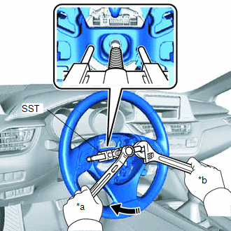
4. REMOVE LOWER STEERING WHEEL COVER NO. 2
Click here
5. REMOVE CRUISE CONTROL MAIN SWITCH
Click here
6. REMOVE STEERING WHEEL SWITCH ASSEMBLY
Click here