Removal
REMOVAL
PRECAUTION / NOTICE / HINT
The procedures required (adjustment, calibration, initialization or registration) after parts are removed, installed or replaced during removal/installation of the vacuum warning switch assembly are indicated below.
Procedure Required After Replacing / Removing / Installing PartsReplacement part or procedure | Required Procedure | Effect/Inoperative function when procedure not performed | Link |
|---|---|---|---|
Disconnect the cable from the negative (-) battery terminal. |
Memorize Steering Angle Neutral Point |
Lane Departure Alert System (with Steering Control) |
 |
Pre-Collision System |
|||
Initialize Back Door Lock |
Door Lock Control System |
|
PROCEDURE
1. REMOVE FRONT WIPER MOTOR AND LINK ASSEMBLY
Click here
2. REMOVE NO. 1 HEATER AIR DUCT SPLASH SHIELD SEAL
Click here
3. REMOVE LH WATER PROTECTION PLATE
Click here
4. REMOVE LH COWL BODY MOUNTING REINFORCEMENT
Click here
5. REMOVE RH COWL BODY MOUNTING REINFORCEMENT
Click here
6. REMOVE COWL TOP OUTER PANEL SUB-ASSEMBLY
Click here
7. REMOVE BATTERY
Click here
8. REMOVE COWL TOP OUTER PANEL SUB-ASSEMBLY
Click here
9. REMOVE VACUUM WARNING SWITCH ASSEMBLY
(a) Disconnect the connector from the vacuum warning switch assembly. |
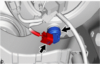 |
(b) Remove the vacuum warning switch assembly from the brake booster assembly.
(c) Remove the check valve grommet from the brake booster assembly.