Electronic Circuit Inspection Procedure
ELECTRONIC CIRCUIT INSPECTION PROCEDURE
BASIC INSPECTION
(a) CONDITIONS FOR MEASURING ELECTRONIC COMPONENT RESISTANCE
(1) Unless otherwise specified, all resistance measurements are standard values measured at an ambient temperature of 20 °C. Results obtained at high temperatures, i.e. immediately after the engine is stopped, may be inaccurate. Therefore, allow the engine to cool down before performing any resistance measurement.
*a |
NG |
*b |
OK |
(b) HANDLING CONNECTORS
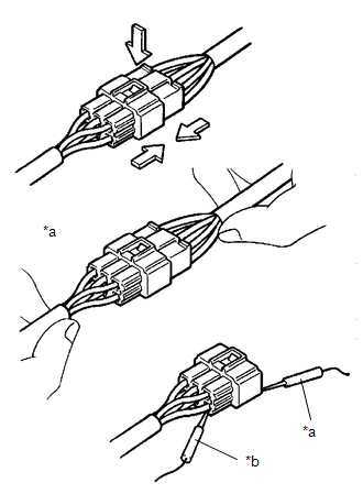
(1) When disconnecting a connector, first firmly squeeze the connector halves together to release the lock, then press down the lock claw and separate the connector.
(2) When disconnecting a connector, do not pull on the wire harnesses. Grasp the connector itself and separate it.
(3) Before reconnecting a connector, make sure the terminals are not deformed, damaged or loose, and that no parts are missing.
(4) To connect a connector, push it in firmly until a click is heard.
(5) When checking a connector with an electrical tester, probe from the rear of the connector (wire harness side) using a miniature test probe.
NOTICE:
- A waterproof connector cannot be checked from the rear. Check it by connecting an auxiliary wire harness.
- Be careful not to damage the terminals by moving the tester probe inside them.
(c) CHECKING CONNECTORS
*a |
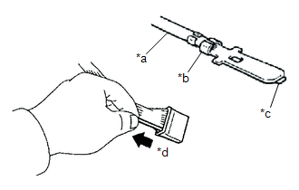
Center wire |
*b |
Crimp loose |
*c |
Terminal deformed |
*d |
Pull gently |
(1) Check with the connector connected: Press on the connectors to check that they are properly connected and securely locked.
(2) Check with the connector disconnected: Check by pulling gently on the wire harness from the rear of the connector. Look for unlocked or missing terminals, loose or bent crimps, or broken conductor wires. Visually check for corrosion, metal or foreign matter, and water, and check whether terminals are bent, rusted, overheated, dirty or deformed.
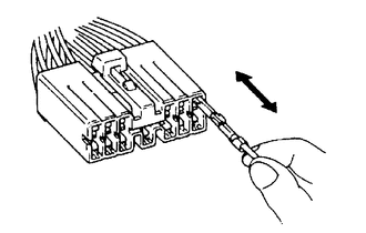
(3) Check the terminal contact pressure: Prepare a spare male terminal. Insert it into the female terminal and check whether the tension is sufficient both during insertion and after full engagement.
NOTICE:
When testing a gold-plated female terminal, always use a gold-plated male terminal.
(d) CONNECTOR TERMINAL REPAIR METHOD
*a |
OK |
*b |
NG |
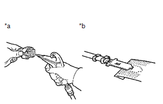
(1) If foreign matter is present on the terminal, clean the contact point with compressed air or a cloth. Never polish the contact point with sandpaper, as the plating may come off.
(2) If the contact pressure is not normal, replace the female terminal. If the male terminal is gold-plated (gold color), use a gold-plated female terminal, and if it is silver-plated (silver color), use a silver-plated female terminal.
(3) Damaged, deformed or corroded terminals must be replaced. If the terminal does not lock properly in the housing, the housing may need to be replaced.
(e) HANDLING WIRE HARNESSES
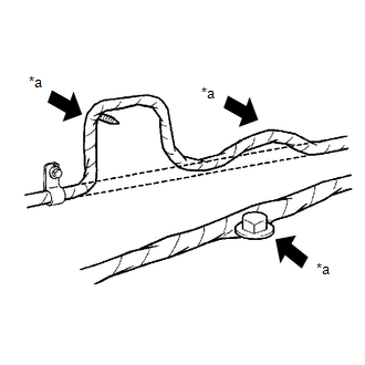
*a |
NG |
(1) Before removing a wire harness, observe the wiring and its clamps so that they can be reinstalled in the same way.
(2) Never twist, pull or loosen the wire harness more than necessary.
(3) The wire harness must never come into contact with high-temperature, rotating, moving, vibrating or sharp parts. Avoid contact with panel edges, screw ends and other sharp points.
(4) When installing parts, never pinch the wire harness between them.
(5) Never cut or break the wire harness protective covering. If it is cut or broken, repair the wire harness with insulating tape or replace it.
CHECKING FOR POSSIBLE OPEN CIRCUITS
(a) To check for an open circuit in the wire harness shown in Fig. 1, measure the resistance and voltage as described below.
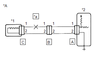
*A |
Fig. 1 |
*1 |
SENSOR |
*2 |
ECU |
*a |
OPEN |
(b) Check the resistance.
(1) Disconnect connectors A and C and measure the resistance between the connector terminals.
Standard resistance (Fig. 2):
Tester Connection | Condition | Specified Condition |
|---|---|---|
Terminal 1 of connector A - Terminal 1 of connector C |
Always |
10 kΩ minimum |
Terminal 2 of connector A - Terminal 2 of connector C |
Always |
Below 1 Ω |
HINT:
Measure the resistance while gently shaking the wire harness vertically and horizontally.
- If the results match the specified values above, there is an open circuit between terminal 1 of connector A and terminal 1 of connector C.
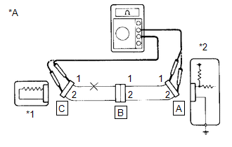
*A |
Fig. 2 |
*1 |
SENSOR |
*2 |
ECU |
(2) Disconnect connector B and measure the resistance between the connector terminals.
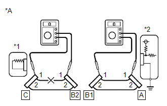
*A |
Fig. 3 |
*1 |
SENSOR |
*2 |
ECU |
Standard resistance (Fig. 3):
Tester Connection | Condition | Specified Condition |
|---|---|---|
Terminal 1 of connector A - Terminal 1 of connector B1 |
Always |
Below 1 Ω |
Terminal 1 of connector B2 - Terminal 1 of connector C |
Always |
10 kΩ minimum |
- If the results match the specified values above, there is an open circuit between terminal 1 of connector B2 and terminal 1 of connector C.
(c) Check the voltage.
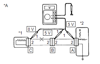
*A |
Fig. 4 |
*1 |
SENSOR |
*2 |
ECU |
(1) In a circuit where voltage is applied to an ECU connector terminal, a short circuit can be detected by checking the voltage.
With all connectors connected, measure the voltage between body ground and the following terminals (in this order): 1) terminal 1 of connector A, 2) terminal 1 of connector B, and 3) terminal 1 of connector C.
Standard voltage (Fig. 4):
Tester Connection | Condition | Specified Condition |
|---|---|---|
Terminal 1 of connector A - Body ground |
Ignition Switch in ON position |
5 V |
Terminal 1 of connector B - Body ground |
Ignition Switch in ON position |
5 V |
Terminal 1 of connector C - Body ground |
Ignition Switch in ON position |
Below 1 V |
- If the results match the specified values above, there is an open circuit in the wire harness between terminal 1 of connector B and terminal 1 of connector C.
CHECK FOR POSSIBLE SHORT CIRCUITS
(a) If a short to ground occurs in a wire in the wire harness (Fig. 5), locate the shorted section by measuring the resistance as follows:
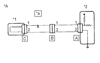
*A |
Fig. 5 |
*1 |
SENSOR |
*2 |
ECU |
*a |
SHORT CIRCUIT |
(b) Check the resistance to body ground.
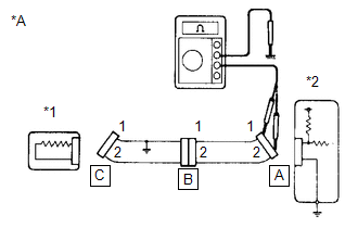
*A |
Fig. 6 |
*1 |
SENSOR |
*2 |
ECU |
(1) Disconnect connectors A and C and measure the resistance.
Standard resistance (Fig. 6):
Tester Connection | Condition | Specified Condition |
|---|---|---|
Terminal 1 of connector A - Body ground |
Always |
Below 1 Ω |
Terminal 2 of connector A - Body ground |
Always |
10 kΩ minimum |
HINT:
Measure the resistance while gently shaking the wire harness vertically and horizontally.
- If the results match the specified values above, there is a short circuit between terminal 1 of connector A and terminal 1 of connector C.
(2) Disconnect connector B and measure the resistance.
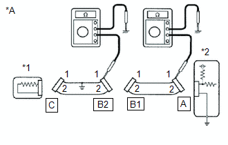
*A |
Fig. 7 |
*1 |
SENSOR |
*2 |
ECU |
Standard resistance (Fig. 7):
Tester Connection | Condition | Specified Condition |
|---|---|---|
Terminal 1 of connector A - Body ground |
Always |
10 kΩ minimum |
Terminal 1 of connector B2 - Body ground |
Always |
Below 1 Ω |
- If the results match the specified values above, there is a short circuit between terminal 1 of connector B2 and terminal 1 of connector C.
INSPECT AND REPLACE ECU
NOTICE:
- Do not disconnect the ECU connector. Perform the inspection from the rear of the connector on the wire harness side.
- Unless otherwise specified, perform the inspection with the engine off and the ignition switch ON.
- Make sure the connectors are fully engaged. Make sure no wires are loose, corroded or broken.
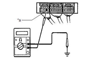
(a) First check the ECU ground circuit. If it is defective, repair it. If it is in good condition, there may be a malfunction in the ECU. In this case, temporarily replace the ECU with a known good one and check whether the symptoms recur. If the symptoms disappear, replace the original ECU.
(1) Measure the resistance between the ECU ground terminal and body ground.
*a |
Ground |
Standard resistance:
Below 1 Ω
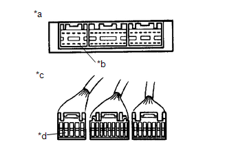
(2) Disconnect the ECU connector. Check the ECU-side and wire-harness-side ground terminals for bent terminals, corrosion or foreign matter. Finally, check the contact pressure of the female terminals.
*a |
Component without wire harness connected (ECU) |
*b |
Ground |
*c |
Front view of wire harness side connector (to ECU) |
*d |
Ground |