Adjustment
ADJUSTMENT
PRECAUTION / NOTICE / HINT
The procedures required after the front wheel alignment procedure (adjustment, calibration and initialization or registration) are shown below.
Procedures Required After Completing the ProcedureReplaced Part or Performed Procedure | Required Procedure | Effect/Inoperative Function When Required Procedure Is Not Performed | Link |
|---|---|---|---|
Front wheel alignment adjustment |
|
|
 |
PROCEDURE
1. CHECK TIRES
Click here
2. MEASURE VEHICLE HEIGHT
NOTICE:
- Before inspecting the wheel alignment, adjust the vehicle ground clearance to the specified value.
- Be sure to perform measurements on a flat surface.
- If it is necessary to go under the vehicle to perform measurements, make sure the parking brake is applied and the vehicle is blocked with chocks.
- Perform the check with the vehicle unloaded.
- The standard value shown here is used when performing wheel alignment and does not indicate the actual height of a vehicle.
(a) Bounce the vehicle at each corner to stabilize the suspension.
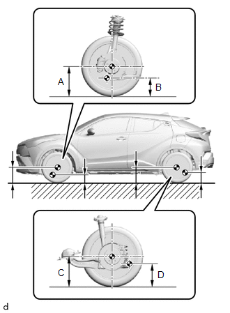
(b) Measure the vehicle height. Measurement points:
Vehicle height (vehicle unloaded):
|
 |
3. INSPECT CAMBER, CASTER AND KINGPIN INCLINATION
NOTICE:
Perform the check with the vehicle unloaded.
(a) Set a camber/caster/kingpin gauge and place the front wheels on the center of the turning radius gauge. |
|
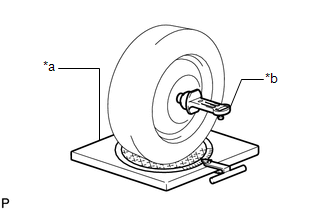
(b) Inspect the camber, caster and kingpin inclination.
Camber (vehicle unloaded):
Vehicle Model | Camber Angle | Left/Right Difference |
|---|---|---|
ZGX10L-AHXEPX ZGX10L-AHXGPX ZGX10L-AHXNPX |
0°06' +/- 0°45' (0,10° +/- 0,75°) |
0°45' (0.75°) maximum |
ZGX10L-BHXNPA |
0°01' +/- 0°45' (0,02° +/- 0,75°) |
0°45' (0.75°) maximum |
Caster (vehicle unloaded):
Vehicle Model | Caster inclination | Left/Right Difference |
|---|---|---|
ZGX10L-AHXEPX ZGX10L-AHXGPX ZGX10L-AHXNPX |
6°36' +/- 0°45' (6,60° +/- 0,75°) |
0°45' (0.75°) maximum |
ZGX10L-BHXNPA |
6°45' +/- 0°45' (6,75° +/- 0,75°) |
0°45' (0.75°) maximum |
Kingpin inclination (vehicle unloaded):
Vehicle Model | Kingpin inclination reference |
|---|---|
ZGX10L-AHXEPX ZGX10L-AHXGPX ZGX10L-AHXNPX |
13°49' (13,82°) |
ZGX10L-BHXNPA |
14°02' (14,03°) |
4. ADJUST CAMBER
NOTICE:
After adjusting the camber, check the toe.
(a) Remove the front wheel.
Click here
(b) Remove the 2 nuts on the lower part of the front shock absorber assembly. NOTICE: Leave the bolts in place. |
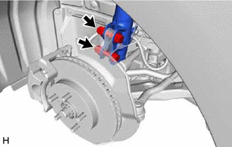 |
(c) Remove the upper and lower bolts one at a time and make sure the steering knuckle can move freely in the front shock absorber assembly.
HINT:
- Reinstall each bolt after removing it and confirm the movement of the steering knuckle.
- If the steering knuckle does not move freely in the front shock absorber assembly, clean the contact surfaces of the front shock absorber assembly and the steering knuckle.
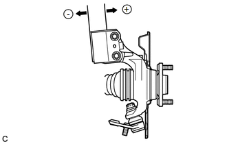
(d) Temporarily install the 2 nuts. (Point A)
(e) Fully push or pull the front axle hub in the direction corresponding to the desired adjustment. (Point B) |
 |
(f) Tighten the 2 nuts. Torque: 270 N·m {2 753 kgf·cm, 199 ft·lbf} NOTICE: Hold the bolts to prevent them from turning when tightening the nuts. |
|
(g) Install the front wheel.
Click here
(h) Bounce the vehicle at the corners to stabilize the suspension.
(i) Check the camber.
Camber (vehicle unloaded):
Vehicle Model | Camber Angle | Left/Right Difference |
|---|---|---|
ZGX10L-AHXEPX ZGX10L-AHXGPX ZGX10L-AHXNPX |
0°06' +/- 0°30' (0,10° +/- 0,50°) |
0°45' (0.75°) maximum |
ZGX10L-BHXNPA |
0°01' +/- 0°30' (0,02° +/- 0,50°) |
0°45' (0.75°) maximum |
(1) If the measured value does not conform to the specifications, calculate the required adjustment using the formula below. Camber adjustment = Center of specified range - Measured value Check the combination of the installed bolts. Select the appropriate bolts by referring to the tables below in order to adjust the camber to the specified values. HINT: Try to adjust the camber to the center of the specified value.
The vehicle body and suspension may be damaged if the camber cannot be correctly adjusted according to the table above. NOTICE: When replacing the bolt, replace the nut with a new one. |
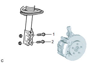 |
(2) Table (1) (To move the axle hub toward the positive side)
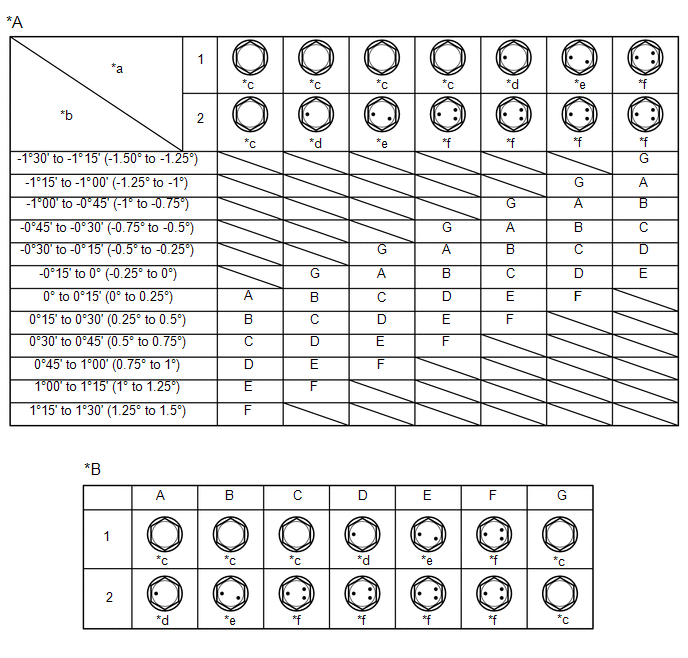
*A |
Table (1) (To move the axle hub toward the positive side) |
*B |
Selected bolt combination |
*a |
Installed bolt |
*b |
Adjustment value |
*c |
Standard Bolt |
*d |
90105-17009 |
*e |
90105-17010 |
*f |
90105-17011 |
(3) Table (2) (To move the axle hub toward the negative side)
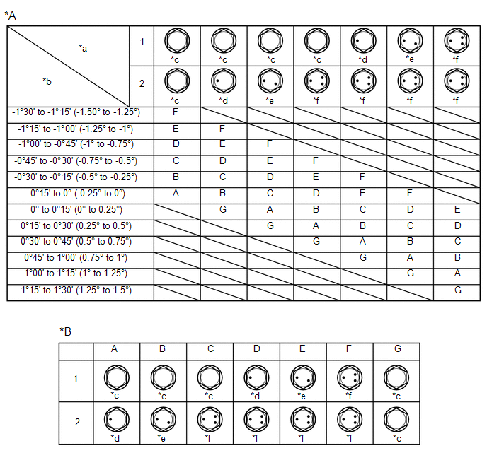
*A |
Table (2) (To move the axle hub toward the negative side) |
*B |
Selected bolt combination |
*a |
Installed bolt |
*b |
Adjustment value |
*c |
Standard Bolt |
*d |
90105-17009 |
*e |
90105-17010 |
*f |
90105-17011 |
(j) If the camber was incorrectly adjusted in the previous step, perform the camber adjustment steps above. During step A, replace the existing bolts with the selected bolts.
HINT:
When replacing both bolts, replace one bolt at a time.
5. INSPECT TOE
NOTICE:
Perform the check with the vehicle unloaded.
(a) Bounce the vehicle at each corner to stabilize the suspension.
(b) Release the parking brake and place the shift lever in N.
(c) Push the vehicle straight forward for approximately 5 m (16.4 ft). (Point C)
(d) Place center line marks on the points farthest from the front wheels and measure the distance between the marks (dimension B).
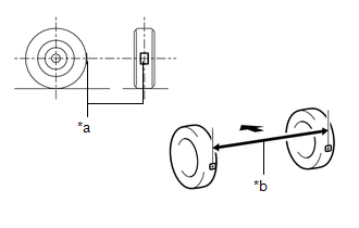
*a |
Center Line Marker |
*b |
Dimension B |
 |
Front of Vehicle |
(e) Slowly push the vehicle straight ahead to turn the front wheels 180°. Use a front tire valve as the reference point.
HINT:
Do not turn the wheels more than 180°. If the wheels turn more than 180°, repeat the procedure from step C.
(f) Measure the distance between the center line marks located at the front of the wheels (dimension A).
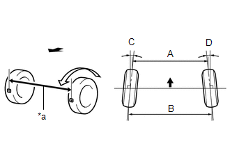
*a |
Dimension A |
|
Front of Vehicle |
Toe (vehicle unloaded):
Vehicle Model | Specified Condition |
|---|---|
ZGX10L-AHXEPX ZGX10L-AHXGPX ZGX10L-AHXNPX |
C + D: 0°06' +/- 0°10' (0,11° +/- 0,17°) |
B - A: 1.3 +/- 2.0 mm (0.0512 +/- 0.0787 in) |
|
ZGX10L-BHXNPA |
C + D: 0°07' +/- 0°10' (0,12° +/- 0,17°) |
B - A: 1.4 +/- 2.0 mm (0.0551 +/- 0.0787 in) |
HINT:
Measure "B - A" only when it is not possible to measure "C + D".
If the toe-in is not within the specified range, adjust it at the steering rack ends.
6. ADJUST TOE-IN
(a) Make sure the thread lengths of the left and right steering rack ends are approximately the same. Standard difference: 1.5 mm (0.0591 in) max. |
|
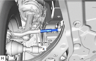
(b) Remove the steering rack boot clamps.
(c) Loosen the tie rod end sub-assembly lock nuts. |
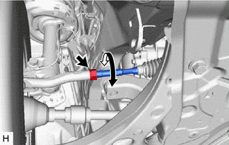 |
(d) Adjust the steering rack ends if the difference in thread length between the left and right steering rack ends is not within the specified range.
(1) If the toe-in measurement is greater than specified (toe-out is excessive), lengthen the shorter steering rack end so that the length difference is within the specified range.
(2) If the toe-in measurement is greater than specified (toe-in is excessive), shorten the longer steering rack end so that the length difference is within the specified range.
(3) Measure the toe-in.
(e) Adjust the toe-in by turning the left and right steering rack ends by the same amount.
Toe (vehicle unloaded):
Vehicle Model | Specified Condition |
|---|---|
ZGX10L-AHXEPX ZGX10L-AHXGPX ZGX10L-AHXNPX |
C + D: 0°06' +/- 0°05' (0,11° +/- 0,08°) |
B - A: 1.3 +/- 1.0 mm (0.0512 +/- 0.0394 in) |
|
ZGX10L-BHXNPA |
C + D: 0°07' +/- 0°05' (0,12° +/- 0,08°) |
B - A: 1.4 +/- 1.0 mm (0.0551 +/- 0.0394 in) |
HINT:
Make adjustments so the value is as close as possible to the center of the specified range.
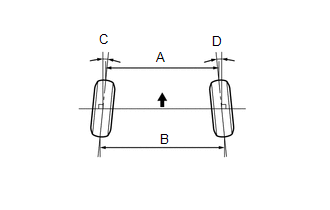
|
Front of Vehicle |
(f) Make sure the thread lengths of the left and right steering rack ends are the same.
(g) Tighten the tie rod end sub-assembly lock nuts.
Torque:
74 N·m {755 kgf·cm, 55 ft·lbf}
(h) Seat the steering rack boots and install the steering rack boot clamps.
HINT:
Make sure the steering rack boots are not twisted.
7. CHECK WHEEL TURNING ANGLE
(a) Place center line marks on the points farthest from a turning radius gauge.
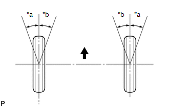
*a |
Inner |
*b |
Outer |
|
Front of Vehicle |
(b) Turn the steering wheel fully to the left and right, then measure the wheel turning angle.
NOTICE:
Perform the check with the vehicle unloaded.
Wheel turning angle (unladen vehicle):
Vehicle Model | Inside wheel | Outside wheel |
|---|---|---|
ZGX10L-AHXEPX ZGX10L-AHXGPX ZGX10L-AHXNPX |
39°30' +/- 2°00' (39,50° +/- 2,00°) |
33°50' (33,83°) |
ZGX10L-BHXNPA |
39°15' +/- 2°00' (39,25° +/- 2,00°) |
33°34' (33,57°) |
- If the left and right inside wheel angles do not meet the specified value, check and adjust the length of the left and right steering rack ends.
8. ALIGN FRONT WHEELS WITH VEHICLE CENTERLINE
9. PERFORM YAW RATE AND ACCELERATION SENSOR CALIBRATION
Click here