Installation
INSTALLATION
PROCEDURE
1. INSTALL INSTRUMENT PANEL SAFETY PADDING SUB-ASSEMBLY
(a) Engage the guides to install the driver's instrument panel cushion sub-assembly as shown in the illustration.
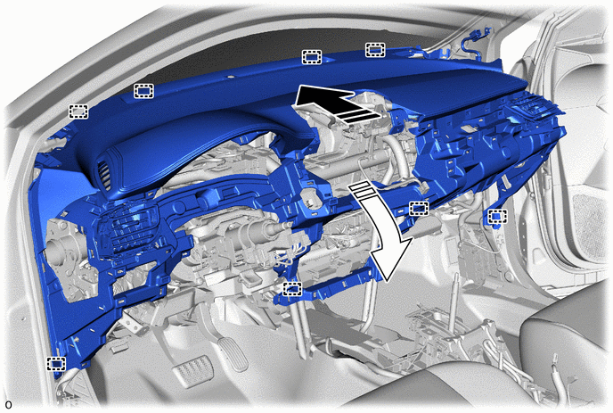
 |
Install in this direction (1) |
 |
Install in this direction (2) |
(b) Engage each fastener.
(c) Connect each connector.
(d) Connect the airbag connector.
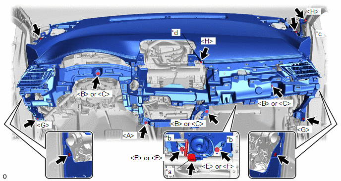
*a |
Airbag connector |
*b |
Airbag bolt |
*c |
Ground bolt A |
*d |
Ground bolt B |
(e) Install the 4 clips.
(f) TMMT-manufactured vehicles:
(1) Install the 10 bolts as shown in the illustration. Torque: Airbag bolt: 20 N·m {204 kgf·cm, 15 ft·lbf} Ground bolt A, for type A: 10.5 N·m {107 kgf·cm, 8 ft·lbf} Ground bolt A, for type B: 10 N·m {102 kgf·cm, 7 ft·lbf} Ground bolt B, for type A: 8.3 N·m {85 kgf·cm, 73 in·lbf} Ground bolt B, for type B: 10 N·m {102 kgf·cm, 7 ft·lbf} |
|
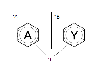
(g) TMC-manufactured vehicles:
(1) Install the 10 bolts as shown in the illustration.
Torque:
Airbag bolt:
20 N·m {204 kgf·cm, 15 ft·lbf}
Ground bolt A:
10 N·m {102 kgf·cm, 7 ft·lbf}
Ground bolt B:
10 N·m {102 kgf·cm, 7 ft·lbf}
2. INSTALL NO. 2 HEATER DUCT SUB-ASSEMBLY WITH DAMPER
(a) Engage the claws to install the No. 2 heater duct sub-assembly as shown in the illustration.
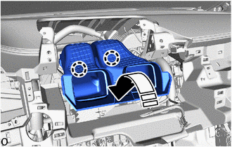
|
Install in this direction |
3. INSTALL NO. 1 INSTRUMENT PANEL SUB-ASSEMBLY (with display)
(a) When installing a new instrument panel sub-assembly: (1) Using nippers, cut both ends of the slider portion shown in the illustration. |
|
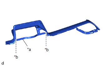
(b) Engage the guides and clips to install the No. 1 instrument panel sub-assembly as shown in the illustration.
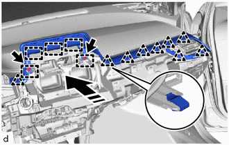
|
Install in this direction |
(c) Install the 2 bolts
4. INSTALL RADIO RECEIVER AND DISPLAY ASSEMBLY WITH BRACKET (for type with radio and display)
Click here
5. INSTALL INSTRUMENT PANEL CENTER REGISTER ASSEMBLY
(a) Engage the guides and claws to install the center instrument panel register assembly as shown in the illustration.
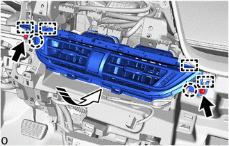
|
Install in this direction |
(b) Install the 2 screws
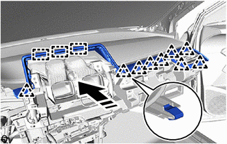
6. INSTALL NO. 1 INSTRUMENT PANEL SUB-ASSEMBLY (without display)
(a) When installing a new instrument panel sub-assembly: (1) Using nippers, cut both ends of the slider portion shown in the illustration. |
|
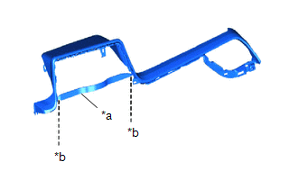
(b) Engage the guides and clips to install the No. 1 instrument panel sub-assembly as shown in the illustration.
|
Install in this direction |
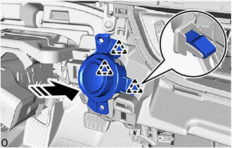
7. INSTALL STARTER SWITCH GARNISH (with smart key system)
(a) Connect the connector.
(b) Engage the clips to install the starter switch garnish as shown in the illustration.
|
Install in this direction |
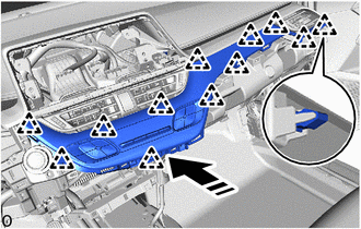
8. INSTALL INSTRUMENT CLUSTER LOWER CENTER FINISH PANEL SUB-ASSEMBLY
(a) Connect the connector.
(b) Engage the clips to install the instrument cluster lower center finish panel sub-assembly as shown in the illustration.
|
Install in this direction |
9. INSTALL NO. 1 RADIO BRACKET (without radio receiver)
(a) Engage the guides to install the No. 1 radio bracket. |
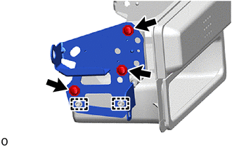 |
(b) Install the 3 screws <D>.
10. INSTALL NO. 2 RADIO BRACKET (without radio receiver)
(a) Engage the guides to install the No. 2 radio bracket. |
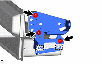 |
(b) Install the 3 screws <D>.
11. INSTALL STEREO INSTALLATION OPENING COVER WITH BRACKET (without radio receiver)
(a) Connect the connector.
(b) Engage the guides to install the stereo installation opening cover with bracket. |
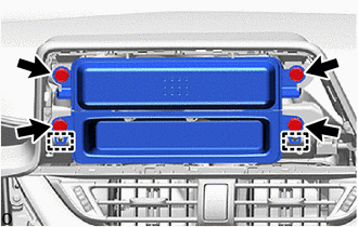 |
(c) Install the 4 bolts
12. INSTALL RADIO RECEIVER ASSEMBLY WITH BRACKET (with radio receiver)
Click here
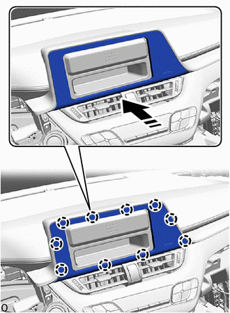
13. INSTALL INSTRUMENT CLUSTER CENTER FINISH PANEL SUB-ASSEMBLY (without display)
(a) Connect the connector.
(b) Engage the claws to install the instrument cluster center finish panel sub-assembly as shown in the illustration.
|
Install in this direction |
14. INSTALL INSTRUMENT PANEL LOWER AIRBAG ASSEMBLY WITH NO. 1 DOOR
Click here
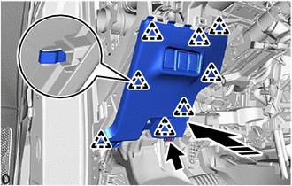
15. INSTALL FUSE BOX OPENING COVER
(a) Connect each connector.
(b) Engage the clips to install the fuse box opening cover as shown in the illustration.
|
Install in this direction |
(c) Install the screw
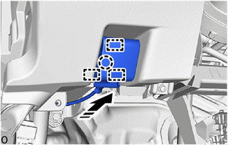
16. CONNECT HOOD LOCK CONTROL LEVER SUB-ASSEMBLY
(a) Engage the guides and claw to connect the hood lock control lever sub-assembly as shown in the illustration.
|
Install in this direction |
17. INSTALL INSTRUMENT CLUSTER ASSEMBLY
Click here
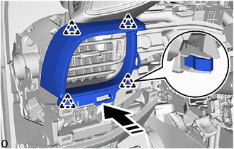
18. INSTALL NO. 2 INSTRUMENT PANEL SUB-ASSEMBLY
(a) Engage the clips to install the No. 2 instrument panel sub-assembly as shown in the illustration.
|
Install in this direction |
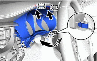
19. INSTALL INSTRUMENT CLUSTER FINISH PANEL ASSEMBLY
(a) Engage the guides and clips to install the instrument cluster finish panel assembly as shown in the illustration.
|
Install in this direction |
(b) Install the 2 clips.
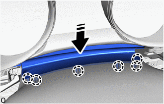
(c) Engage the claws to install the instrument cluster protector spacer as shown in the illustration.
|
Install in this direction |
20. INSTALL INSTRUMENT CLUSTER FINISH PANEL SUB-ASSEMBLY
(a) with switch:
(1) Connect each connector.
(b) Engage the clips to install the instrument cluster finish panel sub-assembly as shown in the illustration.
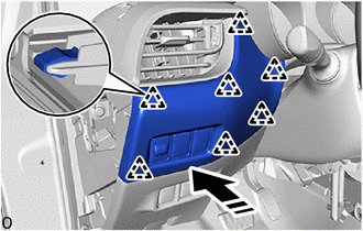
|
Install in this direction |
21. INSTALL NO. 1 INSTRUMENT PANEL SPEAKER PANEL SUB-ASSEMBLY
(a) Connect the connector.
(b) Engage the guides, claws and clips to install the No. 1 instrument panel speaker panel sub-assembly as shown in the illustration.
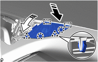
|
Install in this direction (1) |
|
Install in this direction (2) |
22. INSTALL NO. 2 INSTRUMENT PANEL SPEAKER PANEL SUB-ASSEMBLY
HINT:
Use the same procedure as for the No. 1 instrument panel speaker panel sub-assembly.
23. INSTALL FRONT PILLAR GARNISH LH
(a) Remove the adhesive tape and protective cover.
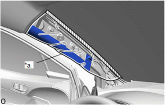
*a |
Protective cover |
 |
Tape |
(b) Install the 2 front pillar garnish clips to the front pillar garnish LH. NOTICE:
|
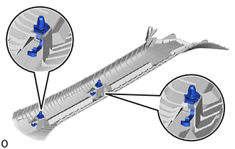 |
(c) Engage the guides as shown in the illustration.
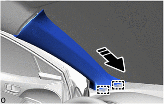
|
Install in this direction |
(d) Engage the clips to install the front pillar garnish LH as shown in the illustration.
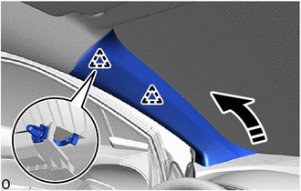
|
Install in this direction |
24. INSTALL FRONT PILLAR GARNISH RH
HINT:
Perform the same procedure as for the left side.
25. INSTALL INSTRUMENT PANEL SIDE PANEL LH
(a) with airbag deactivation switch:
(1) Connect the connector.
(b) Engage the guides and clips to install the instrument panel side panel LH as shown in the illustration.
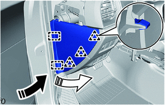
|
Install in this direction (1) |
|
Install in this direction (2) |
26. INSTALL INSTRUMENT PANEL SIDE PANEL RH
HINT:
Perform the same procedure as for the left side.
27. INSTALL INSTRUMENT PANEL FINISH PANEL END LH
(a) Engage the guides and clips to install the instrument panel finish panel end LH as shown in the illustration.
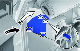
|
Install in this direction (1) |
|
Install in this direction (2) |
28. INSTALL RH INSTRUMENT PANEL FINISH PANEL END PIECE
HINT:
Perform the same procedure as for the left side.
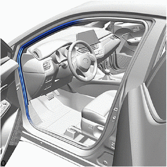
29. CONNECT LH FRONT DOOR OPENING TRIM WEATHERSTRIP
(a) Connect the LH front door opening trim weatherstrip to the area shown in the illustration. |
 |
30. CONNECT RH FRONT DOOR OPENING TRIM WEATHERSTRIP
HINT:
Perform the same procedure as for the left side.
31. INSTALL NO. 2 LOWER INSTRUMENT PANEL FINISH PANEL
(a) Connect the connector.
(b) Engage the clips and claws to install the No. 2 lower instrument panel finish panel, as shown in the illustration.
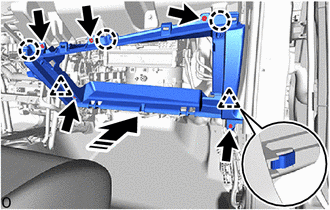
|
Install in this direction |
(c) Install the 5 screws <D>.
32. INSTALL GLOVE BOX DOOR STOPPER SUB-ASSEMBLY
(a) Engage the claw to install the glove box door stopper sub-assembly. |
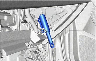 |
33. INSTALL GLOVE BOX DOOR ASSEMBLY
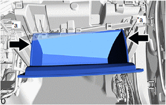
(a) With the glove box door assembly opened approximately 61° from its closed position, engage the 4 hinges horizontally.
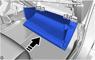
|
Install in this direction |
NOTICE:
- Engaging the hinges from above will deform the hinges.
- Be sure to install the glove box door assembly horizontally.
(b) While pressing the sides of the glove box door assembly in the directions shown by the arrows in the illustration, close the door to engage it with the 2 stoppers. |
|
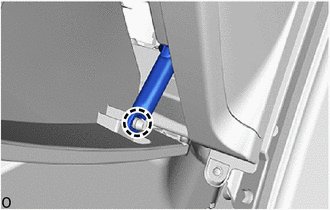
(c) Engage the claw to connect the glove box door stopper sub-assembly. |
 |
34. INSTALL NO. 2 LOWER INSTRUMENT PANEL COVER SUB-ASSEMBLY
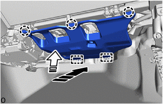
(a) Engage the guides and claws to install the No. 2 lower instrument panel cover sub-assembly as shown in the illustration.
|
Install in this direction (1) |
|
Install in this direction (2) |
35. INSTALL RH ROOF SIDE GARNISH PANEL
HINT:
Perform the same procedure as for the left side.
Click here
36. INSTALL RH FRONT DOOR SILL PLATE
HINT:
Perform the same procedure as for the left side.
Click here
37. INSTALL HEADLIGHT DIMMER SWITCH ASSEMBLY
Click here
38. INSTALL REAR CONSOLE BOX ASSEMBLY
Click here
39. CONNECT CABLE TO NEGATIVE BATTERY TERMINAL
Click here
NOTICE:
When the cable has been disconnected, some systems must be reset after the cable is reconnected.
Click here
40. INSPECT SRS WARNING LIGHT
Click here