Inspection
INSPECTION
PROCEDURE
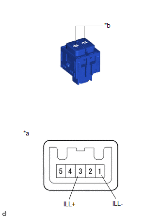
1. INSPECT MULTIPLEX NETWORK MAIN SWITCH ASSEMBLY
(a) Check that the LED lights up.
(1) Apply battery voltage to the multiplex network main switch assembly and check that the LED lights up. OK:
If the result is not as specified, replace the multiplex network switch assembly. |
|
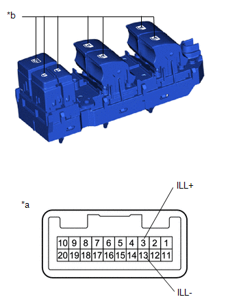
2. INSPECT DOOR CONTROL SWITCH ASSEMBLY (DOOR LOCK CONTROL SWITCH)
(a) Check the operation of the door control switch assembly.
(1) Measure the resistance according to the value(s) shown in the table below. Standard resistance:
If the result is not as specified, replace the door control switch assembly. |
|
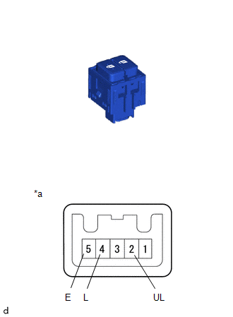
(b) Check that the LED lights up.
(1) Apply battery voltage to the multiplex network main switch assembly and check that the LED lights up. OK:
If the result is not as specified, replace the door control switch assembly. |
|