Valve Clearance Inspection
Table 2.2.1. Main adjustment data
| Engine code | Model 4A-FE | Model 3S-FE |
| Valve clearance (engine cold) | Intake 0.15-0.25 Exhaust 0.25-0.35 | Intake 0.19-0.29 Exhaust 0.28-0.38 |
| Torque specifications, N·m (kgf·m) | Camshaft bearings 13 (1.3) Cylinder head cover 5.9 (0.6) | Camshaft bearings 13 (1.3) Cylinder head cover 5.9 (0.6) |
Procedure · Disconnect the negative battery cable; · Disconnect the PCV hoses from the camshaft cover; · Remove the bolts and the wiring harness protector from the right side of the camshaft cover; · Release the high-tension leads from the clips and disconnect them from the spark plugs; · Release the wiring harness on the right side of the camshaft cover (disconnect it from the generator and the oil pressure sensor), and release all other wire and cable clips; · Remove the cap nuts and washers, then remove the camshaft cover. The crankshaft pulley has a notch, and the lower timing cover has marks spaced at 5° intervals (Fig. 2.2.1). Alignment of the pulley notch with the "0°" mark indicates that pistons in cylinders 1 and 4 are at TDC.
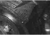
Fig. 2.2.1 Timing marks on the crankshaft pulley and lower timing cover
· Using a wrench or socket with a breaker bar, turn the crankshaft clockwise by the pulley nut until the pulley notch aligns with the "0°" mark.
· Check that the hole in the camshaft pulley aligns with the mark on the bearing cap (Fig. 2.2.2). If not, turn the crankshaft one more full revolution (360°). Only then will piston 1 be on the compression stroke.
· Using a flat feeler gauge, check the clearances between the valve lifter shim and the cam lobes of the corresponding camshafts for the following valves: intake valves of cylinders No. 1 and No. 2; exhaust valves of cylinders No. 1 and No. 3.
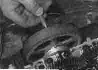
Fig. 2.2.2 Checking camshaft TDC position using a metal rod
· Record the clearance if it is incorrect.
· Turn the camshaft another full revolution (360°) and align the groove on the camshaft pulley with the "0" mark on the lower timing cover.
· Next, check the clearances between the cam lobes and lifters in the same way for the following valves: intake valves of cylinders No. 3 and No. 4; exhaust valves of cylinders No. 2 and No. 4.
Record the clearance if it is incorrect.
Test yourself
A quick Toyota Carina quiz: every answer comes with an explanation and a link to the manual page.