Steering Pad Switch Circuit
DESCRIPTION
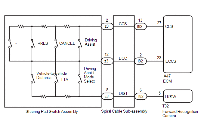
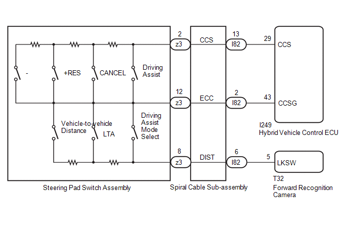
- ECM*1 or hybrid vehicle control ECU*2 performs cruise control based on signals from the driving assist switch, +RES switch, -switch, CANCEL switch (steering pad switch assembly).
- Forward recognition camera changes the driving support mode, turns LTA ON/OFF, and sets the vehicle-to-vehicle distance based on signals from the driving assist mode select switch, LTA switch, and vehicle-to-vehicle distance switch (steering pad switch assembly).
- *1: for Gasoline Model
- *2: for HEV Model
WIRING DIAGRAM
for Gasoline Model
for HEV Model
NOTICE:
- The vehicle is equipped with a Supplemental Restraint System (SRS) which includes components such as airbags. Before servicing (including removal or installation of parts), be sure to read the precaution for Supplemental Restraint System.
Click here

- When replacing the forward recognition camera, always replace it with a new one. If a forward recognition camera which was installed to another vehicle is used, the information stored in the forward recognition camera will not match the information from the vehicle and a DTC may be stored.
- When the forward recognition camera has been replaced with a new one, make sure to clear all stored vehicle control history of each system and the forward recognition camera beam axis alignment data.
HINT:
Forward recognition camera beam axis alignment can be performed by using "One Time Recognition", "Driving Adjustment" or "Camera Axis Adjustment Value Write".
One Time Recognition: Click here
Driving Adjustment: Click here
Camera Axis Adjustment Value Write: Click here
- If the forward recognition camera has been replaced with a new one, make sure to perform Software Version Confirmation.
Click here
- for Gasoline Model
Before replacing the ECM, refer to Registration.
Click here
- for HEV Model
Before replacing the hybrid vehicle control ECU, refer to Registration.
Click here
PROCEDURE
CONFIRM PROBLEM SYMPTOMS
(a) Check the problem symptoms.
Result | Proceed to |
|---|---|
All switches cannot be operated |
A |
Driving assist switch, +RES switch, -Switch, CANCEL switch cannot be operated |
B |
Only driving assist switch cannot be operated |
C |
Only +RES switch cannot be operated |
|
Only -switch cannot be operated |
|
Only CANCEL switch cannot be operated |
|
Only driving assist mode select switch cannot be operated |
|
Only vehicle-to-vehicle distance switch cannot be operated |
|
Only LTA switch cannot be operated |
|
Driving assist mode select switch, vehicle-to-vehicle distance switch, and LTA switch cannot be operated |
D |
| B |  |
GO TO STEP 6 |
| C | |
REPLACE STEERING PAD SWITCH ASSEMBLY |
| D | |
GO TO STEP 10 |
|

INSPECT STEERING PAD SWITCH ASSEMBLY
Click here
| NG | |
REPLACE STEERING PAD SWITCH ASSEMBLY |
|
INSPECT SPIRAL CABLE SUB-ASSEMBLY
Click here
Result | Proceed to |
|---|---|
OK (for Gasoline Model) |
A |
OK (for HEV Model) |
B |
NG |
C |
| B | |
GO TO STEP 5 |
| C | |
REPLACE SPIRAL CABLE SUB-ASSEMBLY |
|
CHECK HARNESS AND CONNECTOR (SPIRAL CABLE SUB-ASSEMBLY - ECM)
(a) Disconnect the A47 ECM connector.
(b) Measure the resistance according to the value(s) in the table below.
Standard Resistance:
Tester Connection | Condition | Specified Condition |
|---|---|---|
I82-2 (ECC) - A47-28 (ECCS) |
Always |
Below 1 Ω |
I82-2 (ECC) or A47-28 (ECCS) - Body ground |
Always |
10 kΩ or higher |
| OK | |
PROCEED TO NEXT SUSPECTED AREA SHOWN IN PROBLEM SYMPTOMS TABLE |
| NG | |
REPAIR OR REPLACE HARNESS OR CONNECTOR |
CHECK HARNESS AND CONNECTOR (SPIRAL CABLE SUB-ASSEMBLY - HYBRID VEHICLE CONTROL ECU)
(a) Disconnect the I249 hybrid vehicle control ECU connector.
(b) Measure the resistance according to the value(s) in the table below.
Standard Resistance:
Tester Connection | Condition | Specified Condition |
|---|---|---|
I82-2 (ECC) - I249-43 (CCSG) |
Always |
Below 1 Ω |
I82-2 (ECC) or I249-43 (CCSG) - Body ground |
Always |
10 kΩ or higher |
| OK | |
PROCEED TO NEXT SUSPECTED AREA SHOWN IN PROBLEM SYMPTOMS TABLE |
| NG | |
REPAIR OR REPLACE HARNESS OR CONNECTOR |
INSPECT STEERING PAD SWITCH ASSEMBLY
Click here
| NG | |
REPLACE STEERING PAD SWITCH ASSEMBLY |
|
INSPECT SPIRAL CABLE SUB-ASSEMBLY
Click here
Result | Proceed to |
|---|---|
OK (for Gasoline Model) |
A |
OK (for HEV Model) |
B |
NG |
C |
| B | |
GO TO STEP 9 |
| C | |
REPLACE SPIRAL CABLE SUB-ASSEMBLY |
|
CHECK HARNESS AND CONNECTOR (SPIRAL CABLE SUB-ASSEMBLY - ECM)
(a) Disconnect the A47 ECM connector.
(b) Measure the resistance according to the value(s) in the table below.
Standard Resistance:
Tester Connection | Condition | Specified Condition |
|---|---|---|
I82-13 (CCS) - A47-27 (CCS) |
Always |
Below 1 Ω |
I82-13 (CCS) or A47-27 (CCS) - Body ground |
Always |
10 kΩ or higher |
| OK | |
REPLACE ECM |
| NG | |
REPAIR OR REPLACE HARNESS OR CONNECTOR |
CHECK HARNESS AND CONNECTOR (SPIRAL CABLE SUB-ASSEMBLY - HYBRID VEHICLE CONTROL ECU)
(a) Disconnect the I249 hybrid vehicle control ECU connector.
(b) Measure the resistance according to the value(s) in the table below.
Standard Resistance:
Tester Connection | Condition | Specified Condition |
|---|---|---|
I82-13 (CCS) - I249-29 (CCS) |
Always |
Below 1 Ω |
I82-13 (CCS) or I249-29 (CCS) - Body ground |
Always |
10 kΩ or higher |
| OK | |
REPLACE HYBRID VEHICLE CONTROL ECU |
| NG | |
REPAIR OR REPLACE HARNESS OR CONNECTOR |
INSPECT STEERING PAD SWITCH ASSEMBLY
Click here
| NG | |
REPLACE STEERING PAD SWITCH ASSEMBLY |
|
INSPECT SPIRAL CABLE SUB-ASSEMBLY
Click here
| NG | |
REPLACE SPIRAL CABLE SUB-ASSEMBLY |
|
CHECK HARNESS AND CONNECTOR (SPIRAL CABLE SUB-ASSEMBLY - FORWARD RECOGNITION CAMERA)
(a) Disconnect the T32 forward recognition camera connector.
(b) Measure the resistance according to the value(s) in the table below.
Standard Resistance:
Tester Connection | Condition | Specified Condition |
|---|---|---|
I82-6 (DIST) - T32-5 (LKSW) |
Always |
Below 1 Ω |
I82-6 (DIST) or T32-5 (LKSW) - Body ground |
Always |
10 kΩ or higher |
| OK | |
REPLACE FORWARD RECOGNITION CAMERA |
| NG | |
REPAIR OR REPLACE HARNESS OR CONNECTOR |