Vanity Light Switch
Inspection
INSPECTION
PROCEDURE
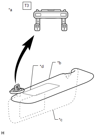
1. INSPECT VANITY LIGHT SWITCH LH (VISOR ASSEMBLY LH)
(a) Check the resistance.
(1) Measure the resistance according to the value(s) in the table below. Standard Resistance:
If the result is not as specified, replace the vanity light switch LH (visor assembly LH). |
|
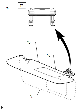
2. INSPECT VANITY LIGHT SWITCH RH (VISOR ASSEMBLY RH)
(a) Check the resistance.
(1) Measure the resistance according to the value(s) in the table below. Standard Resistance:
If the result is not as specified, replace the vanity light switch RH (visor assembly RH). |
|
Installation
INSTALLATION
COMPONENTS (INSTALLATION)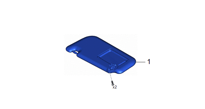
Procedure | Part Name Code |  |  |  |
|
|---|---|---|---|---|---|
1 |
VANITY LIGHT SWITCH (VISOR ASSEMBLY) |
74320 |
- |
- |
- |
HINT:
- Use the same procedure for the RH side and LH side.
- The following procedure is for the LH side.
PROCEDURE
1. INSTALL VANITY LIGHT SWITCH (VISOR ASSEMBLY)