Use the same procedures for the lh side and rh side.
The procedures listed below are for the lh side.
Disconnect cable from negative battery terminal
Caution:Wait at least 90 seconds after disconnecting the cable from the negative (-) battery terminal to prevent airbag and seat belt pretensioner activation.
Remove rear wheel
Remove deck trim side panel assembly lh
Remove the deck trim side panel lh (see page ir- 26).
Hint:
Refer to the procedures from the removal of the rear door scuff plate lh up until the removal of the deck trim side panel assembly lh.
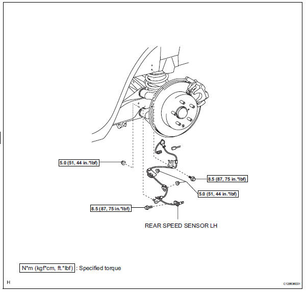
Remove rear speed sensor lh
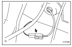
Disconnect the speed sensor connector.
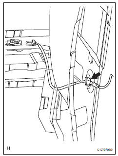
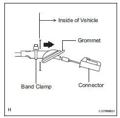
Disconnect the grommet of the speed sensor wire from the hole of the wheel house.
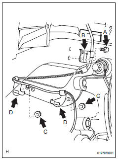
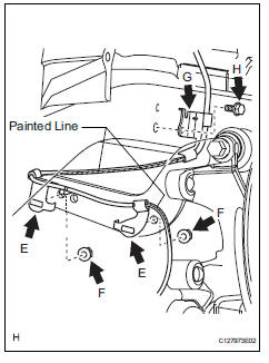
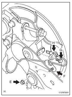
Remove the bolt (labeled a) and sensor clamp (labeled b) from the side member.
Remove the 2 nuts (labeled c) and sensor clamps (labeled d) from the upper arm.
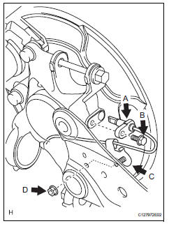
Remove the nut (labeled e) and sensor clamp (labeled f) from the trailing arm.
Remove the bolt (labeled g) and sensor body (labeled h) from the carrier.
Notice:
Keep the sensor tip and sensor installation hole free from foreign matter.
Inspection
Inspect rear speed sensor
Check the speed sensor. If any of the following occurs, replace the speed sensor with a new one.
The surface of the speed sensor is cracked, dented, or chipped off.
The connector or wire harness is scratched, cracked, or damaged.
The speed sensor has been dropped.
InstallationHint:
Use the same procedures for the lh side and rh side.
The procedures listed below are for the lh side.
Install rear speed sensor lh
Notice:
To prevent interference with other parts, do not twist the sensor wire's painted line areas when installing it.
Install the sensor (labeled a) with the bolt (labeled b).
Torque: 8.5 N*m (87 kgf*cm, 75 in.*Lbf)Notice:
Keep the sensor tip and sensor installation hole free from foreign matter.
To prevent interference with the bearing rotor, do not rotate the sensor body when inserting the sensor body or after inserting the sensor body.
Install the sensor clamp (labeled c) with the nut (labeled d).
Torque: 5.0 N*m (51 kgf*cm, 44 in.*Lbf)
Install the sensor clamps (labeled e) with the 2 nuts (labeled f).
Torque: 5.0 N*m (51 kgf*cm, 44 in.*Lbf)Notice:
Do not twist the sensor wire when installing the clamps.
Install the sensor clamp (labeled g) with the bolt (labeled h).
Torque: 8.5 N*m (87 kgf*cm, 75 in.*Lbf)Notice:
Do not twist the sensor wire when installing the clamp.
Insert the connector and grommet to the inside of the vehicle through the passage hole in the wheel house.
Notice:
Make sure the grommet's band clamp remains on the outside of the vehicle.
Hold the grommet and pull it from the inside of the vehicle to the outside of the vehicle. Then fix it in place so that it is not tilted.
Notice:
When pulling out the grommet, do not grip the sensor wire.
Fix the grommet in place within the range shown in the illustration.
Connect the speed sensor connector.
Install deck trim side panel assembly lh
Install the deck trim side panel lh (see page ir-49).
Hint:
Refer to the procedures from the installation of the deck trim side panel lh up until the installation of the rear door scuff plate lh.
Install rear wheel
Torque: 103 n*m (1,050 kgf*cm, 76 ft.*Lbf)
Connect cable to negative battery terminal
Check speed sensor signal
Check the speed sensor signal (see page bc-28).
?
Test yourself
A quick Toyota RAV4 quiz: every answer comes with an explanation and a link to the manual page.