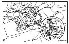
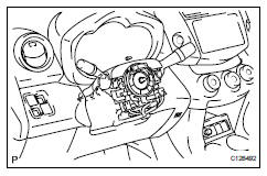
Components RemovalCaution:Some of these service operations affect the srs airbag system. Read the precautionary notices concerning the srs airbag system before servicing the steering column (see page rs-1).
Place front wheels facing straight ahead
Disconnect cable from negative battery terminal
Caution:Wait at least 90 seconds after disconnecting the cable from the negative (-) battery terminal to prevent airbag and seat belt pretensioner activation.
Remove steering pad (see page rs-336)
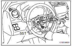
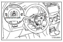
Remove steering wheel assembly
Remove the nut and place matchmarks on the steering wheel and steering column.
Apply a small amount of grease to the threads and tip of sst (center bolt) before use.
Remove steering column cover
Detach the 4 claws, release the tilt lever and remove the lower steering column cover.
Detach the claw and remove the upper steering column cover.
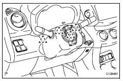
Remove spiral cable sub-assembly
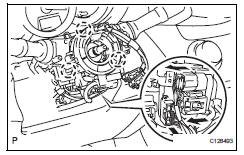
Disconnect all connectors from the turn signal switch with spiral cable.
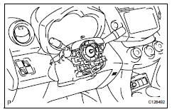
Remove combination switch assembly
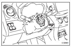
Detach the clamp shown in the illustration and remove the combination switch from the steering column.
Remove instrument panel sub-assembly
Remove the instrument panel (see page ip-4).
Disconnect power steering ecu
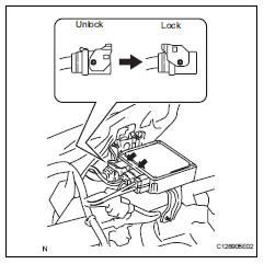
Detach the power steering motor wire harness and torque sensor wire harness clamps from the power steering ecu side.
Disconnect the 2 steering column connectors from the power steering ecu.
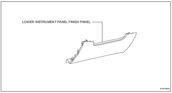
Remove lower instrument panel finish panel (see page ip-20)
Remove column hole cover silencer sheet
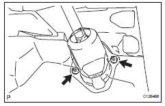
Turn back the floor carpet, remove the 2 clips and remove the column hole cover silencer sheet.
Remove no. 2 Steering intermediate shaft assembly
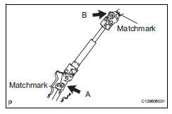
Place matchmarks on the steering intermediate shaft and steering gear
Remove bolt a and detach the steering assembly from the steering gear.
Place matchmarks on the steering intermediate shaft and steering column.
Remove bolt b and detach the steering intermediate shaft shaft from the steering column.
Remove brake pedal support assembly
Remove the brake pedal support (see page br-12).
Remove steering column assembly
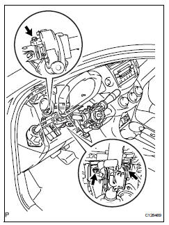
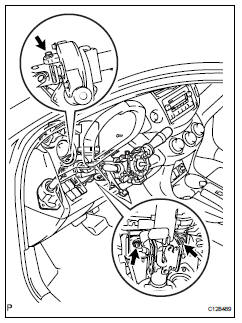
Disconnect all connectors and detach all wire harness clamps from the steering column.
Remove the bolt and 2 nuts and remove the steering column from the instrument panel reinforcement.
Disassembly
Remove transponder key amplifier
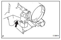
Detach the 2 claws and slide the transponder key amplifier in the direction shown in the illustration, to detach it from the steering column upper with switch bracket.
Remove steering column upper with switch bracket assembly
Fix the steering post in a vise between aluminum plates.
Notice:
Do not overtighten the vise.
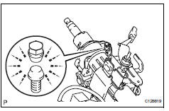
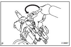
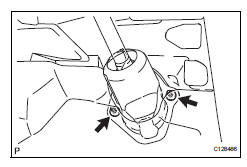
Using a drill, drill a hole in each of the steering lock set bolt to insert a screw extractor.
Using a screw extractor, remove the steering lock set bolt and remove the steering column upper with switch bracket and steering column clamp upper.
Remove ignition switch lock cylinder assembly
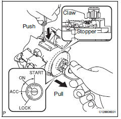
Turn the ignition switch to on (acc).
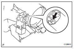
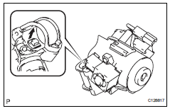
Insert the tip of a screwdriver into the hole in the steering column bracket upper, as shown in the illustration, and pull the ignition switch lock cylinder out until its claw comes into contact with the stopper of the steering column bracket upper.
Notice:
Pull the ignition switch lock cylinder assembly out until its claw comes into contact with the stopper of the steering column bracket assembly upper. Otherwise, the following procedure cannot be conducted properly.
Insert the tip of a screwdriver into the hole in the steering column bracket and tilt it downward, as shown in the illustration, to disengage the claw of the ignition switch lock cylinder. Then pull out the ignition switch lock cylinder.
Remove unlock warning switch assembly
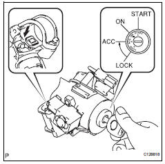
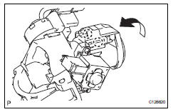
push up the unlock warning switch center portion to disengage the 2 claws.
Hint:
Slide the unlock warning switch in the direction shown by the arrow in the illustration to remove it.
Remove key interlock solenoid
For automatic transaxle:
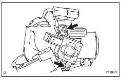
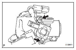
Remove the 2 screws and remove the key interlock solenoid from the steering column bracket upper.
Remove ignition or starter switch assembly
Detach the 2 claws and remove the ignition (starter) switch from the steering column bracket upper.
Inspection
Check torque sensor
Check the torque sensor (see page ps-19).
Check power steering motor
Check the power steering motor (see page ps-22).
Check motor rotation angle sensor
Check the motor rotation angle sensor (see page ps-25).
Reassembly
Install ignition or starter switch assembly
Attach the 2 claws to install the ignition switch onto the steering column bracket upper.
Install key interlock solenoid
For automatic transaxle:
Install the key interlock solenoid onto the steering column bracket upper with the 2 screws.
Install unlock warning switch assembly
Attach the 2 claws to install the unlock warning switch onto the steering column bracket upper.
Hint:
Slide the unlock warning switch in the direction shown by the arrow in the illustration to install it.
Install ignition switch lock cylinder assembly
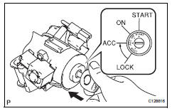
Turn the ignition switch to on (acc).
Install the ignition switch lock cylinder into the steering column bracket upper.
Make sure that the ignition switch lock cylinder is securely fixed onto the ignition switch lock cylinder.
Inspect steering lock operation
Remove the key and check that the steering lock function is activated.
Insert the key, turn the ignition switch on (acc) and check that the steering lock function is deactivated.
Fix the steering column assembly in a vise between aluminum plates.
Notice:
Do not overtighten the vise.
Install the steering column upper with switch bracket and steering column clamp upper with new steering lock set bolt, and then tighten the bolts until their heads come off.
Install transponder key amplifier
Attach the 2 claws and install the transponder key amplifier onto the steering column upper with the switch bracket.
Installation
Install steering column assembly
Install the steering column onto the instrument panel reinforcement with the 3 bolts.
Torque: 25 n*m (255 kgf*cm, 18 ft.*Lbf)
Connect all the connectors and clamp the wire harnesses onto the steering column bracket.
Install brake pedal support assembly
Install the brake pedal support (see page br-16).
Install no.2 Steering intermediate shaft assembly
Align the matchmarks on steering intermediate shaft and the steering sliding yoke and temporarily install them with bolt b.
Torque: 35 n*m (360 kgf*cm, 26 ft.*Lbf)
Align the matchmarks on the steering sliding yoke and steering gear and install them with bolt a.
Torque: 35 n*m (360 kgf*cm, 26 ft.*Lbf)
Install column hole cover silencer sheet
Install the column hole cover plate with the 2 clips.
Install the floor carpet.
Install lower instrument panel finish panel (see page ip-25)
Connect power steering ecu
Connect the 2 steering column connectors to the power steering ecu.
Install the power steering motor wire harness and torque sensor wire harness clamps onto the side of the power steering ecu.
Tilt the steering column assembly up and down to make sure that the power steering motor wire harness and torque sensor wire harness do not interfere with any components.
Install instrument panel sub-assembly
Install the instrument panel (see page ip-9).
Install combination switch assembly
Install the turn signal switch onto the steering column with the clamp.
Install spiral cable sub-assembly
Install the spiral cable onto the turn signal switch.
Connect all the connectors to the turn signal switch with spiral cable.
Install steering column cover
Attach the claw to install the upper steering column cover.
Attach the 4 claws to install the lower steering column cover.
Install steering wheel assembly
Align the matchmarks and install the steering wheel onto the steering column.
Install the nut.
Torque: 50 n*m (510 kgf*cm, 37 ft.*Lbf)
Connect all the connectors to the spiral cable.
Install steering pad (see page rs-336)
Position front wheels facing straight ahead
Connect cable to negative battery terminal
Inspect srs warning light
Inspect the srs warning light (see page rs-52).
?
Test yourself
A quick Toyota RAV4 quiz: every answer comes with an explanation and a link to the manual page.