SFR Solenoid Circuit
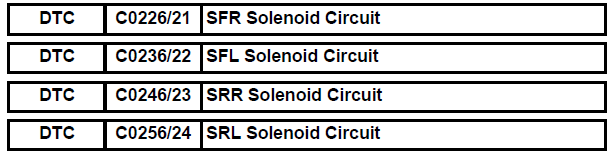
DESCRIPTION
The solenoid comes on when signals are received from the ECU and controls the pressure acting on the wheel cylinders, thus controlling brake force.
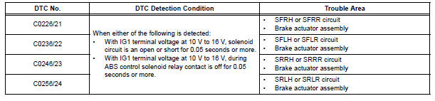
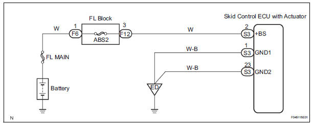
WIRING DIAGRAM
INSPECTION PROCEDURE
1 RECONFIRM DTC
HINT: These codes are detected when a problem is identified in the brake actuator.
The solenoid circuit is in the brake actuator.
Therefore, solenoid circuit inspection and solenoid unit inspection cannot be performed. Be sure to check if any DTC is output before replacing the brake actuator assembly.
(a) Clear the DTCs (See page BC-10).
(b) Start the engine.
(c) Drive the vehicle at the speed of 6 km/h or more.
(d) Check that the same DTCs are recorded (See page BC- 10).
HINT: If a speed signal of 6 km/h or more is input to the skid control ECU, with the ignition switch on and the stop light switch off, the ECU performs self-diagnosis of the motor and solenoid circuits.
Result 
HINT:
- If any DTCs are output while jiggling a connector or wire harness of the brake actuator (skid control ECU), inspect and repair the connector or wire harness.
- If the normal system code is output, slightly jiggle the connectors, wire harnesses, and fuses of the brake actuator assembly. Make sure that no DTCs are output.
- These DTCs may be stored due to a malfunction in the connector terminal connection, etc.


REPLACE BRAKE ACTUATOR ASSEMBLY
Test yourself
A quick Toyota Sienna quiz: every answer comes with an explanation and a link to the manual page.