Terminals of ECU
1. MULTIPLEX NETWORK GATEWAY ECU
- Disconnect the G4 ECU connector.
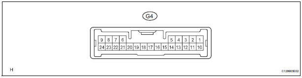
- Measure the voltage between the specified terminals on the wire harness side connector.

If the result is not as specified, there may be a malfunction on the wire harness side.
- Measure the resistance between the specified terminals on the wire harness side connector.

If the result is not as specified, there may be a malfunction on the wire harness side.
2. MULTIPLEX NETWORK BODY ECU
- Disconnect the B7 ECU, 1A, 1C, 1E, 1K and 1L junction block connectors
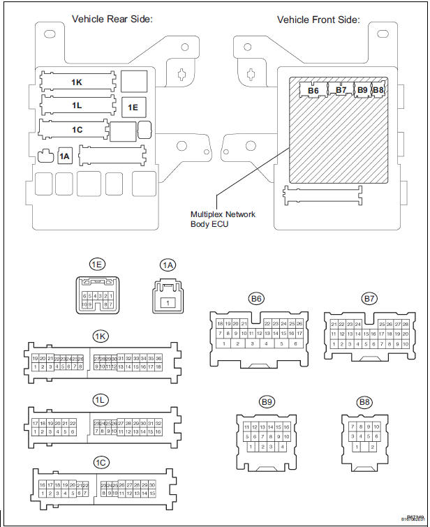
- Measure the voltage between the specified terminals on the wire harness side connector.

If the result is not as specified, there may be a malfunction on the wire harness side.
- Measure the resistance between the specified terminals on the wire harness side connector
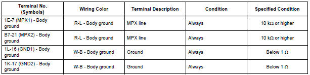
If the result is not as specified, there may be a malfunction on the wire harness side.
3. AIRBAG SENSOR ASSEMBLY
- Disconnect the A21 ECU connector.
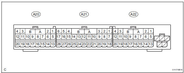
- Measure the voltage between the specified terminals on the wire harness side connector.

If the result is not as specified, there may be a malfunction on the wire harness side.
- Measure the resistance between the specified terminals on the wire harness side connector.
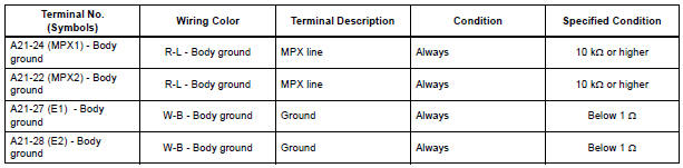
If the result is not as specified, there may be a malfunction on the wire harness side.
4. SEAT POSITION CONTROL ECU (with Driving Position Memory)
- Disconnect the P58 and P59 ECU connectors.
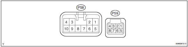
- Measure the voltage between the specified terminals on the wire harness side connector.

If the result is not as specified, there may be a malfunction on the wire harness side.
- Measure the resistance between the specified terminals on the wire harness side connector.

If the result is not as specified, there may be a malfunction on the wire harness side.
5. AIR CONDITIONING AMPLIFIER
- Disconnect the A9 ECU connector.
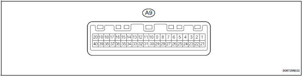
- Measure the voltage between the specified terminals on the wire harness side connector.
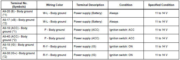
If the result is not as specified, there may be a malfunction on the wire harness side.
- Measure the resistance between the specified terminals on the wire harness side connector.

HINT:
*1: for Automatic A/C
*2: for Manual A/C
If the result is not as specified, there may be a malfunction on the wire harness side.
6. COMBINATION METER
- Disconnect the C10 ECU connector.

- Measure the voltage between the specified terminals on the wire harness side connector.

If the result is not as specified, there may be a malfunction on the wire harness side.
- Measure the resistance between the specified terminals on the wire harness side connector.

If the result is not as specified, there may be a malfunction on the wire harness side.
7. POWER SLIDE DOOR ECU RH
- Disconnect the P27 and P28 ECU connectors.
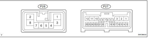
- Measure the voltage between the specified terminals on the wire harness side connector.


If the result is not as specified, there may be a malfunction on the wire harness side.
- Measure the resistance between the specified terminals on the wire harness side connector.

If the result is not as specified, there may be a malfunction on the wire harness side.
8. POWER SLIDE DOOR ECU LH
- Disconnect the P25 and P26 ECU connectors.

- Measure the voltage between the specified terminals on the wire harness side connector.

If the result is not as specified, there may be a malfunction on the wire harness side.
- Measure the resistance between the specified terminals on the wire harness side connector.

If the result is not as specified, there may be a malfunction on the wire harness side.
9. POWER BACK DOOR ECU
- Disconnect the P13 and P14 ECU connectors.
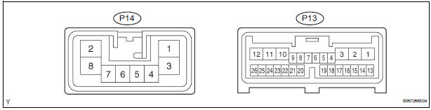
- Measure the voltage between the specified terminals on the wire harness side connector.

If the result is not as specified, there may be a malfunction on the wire harness side.
- Measure the resistance between the specified terminals on the wire harness side connector.

If the result is not as specified, there may be a malfunction on the wire harness side.
10. OUTER MIRROR CONTROL ECU RH (with Driving Position Memory)
- Disconnect the O11 ECU connector.
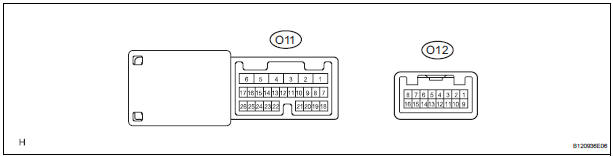
- Measure the voltage between the specified terminals on the wire harness side connector.


If the result is not as specified, there may be a malfunction on the wire harness side.
- Measure the resistance between the specified terminals on the wire harness side connector.

If the result is not as specified, there may be a malfunction on the wire harness side.
11. OUTER MIRROR CONTROL ECU LH (with Driving Position Memory)
- Disconnect the O9 ECU connector.
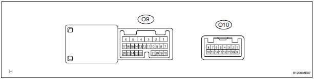
- Measure the voltage between the specified terminals on the wire harness side connector.

If the result is not as specified, there may be a malfunction on the wire harness side.
- Measure the resistance between the specified terminals on the wire harness side connector

If the result is not as specified, there may be a malfunction on the wire harness side.
Test yourself
A quick Toyota Sienna quiz: every answer comes with an explanation and a link to the manual page.