Clearance Sonar Main Switch
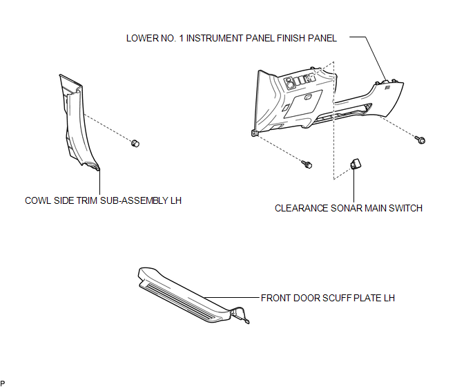
Removal REMOVAL PROCEDURE
1. REMOVE FRONT DOOR SCUFF PLATE LH

2. REMOVE COWL SIDE TRIM SUB-ASSEMBLY LH
3. REMOVE LOWER NO. 1 INSTRUMENT PANEL FINISH PANEL
4. REMOVE CLEARANCE SONAR MAIN SWITCH
(a) Disengage the 2 claws and remove the clearance sonar main switch. |
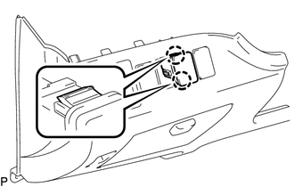 |
1. INSPECT BACK SONAR OR CLEARANCE SONAR SWITCH ASSEMBLY
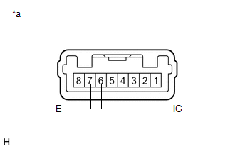
(a) Measure the resistance according to the value(s) in the table below. Standard Resistance:
If the result is not as specified, replace the back sonar or clearance sonar switch assembly. |
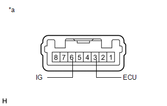 |
(b) Check that the switch illuminates.
(1) Apply battery voltage to the back sonar or clearance sonar switch assembly and check that the switch illuminates. OK:
If the result is not as specified, replace the back sonar or clearance sonar switch assembly. |
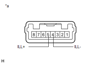 |
(c) Check switch indicator operation.
(1) Apply battery voltage to the back sonar or clearance sonar switch assembly and check that the switch indicator illuminates. OK:
If the result is not as specified, replace the back sonar or clearance sonar switch assembly. |
 |
1. INSTALL CLEARANCE SONAR MAIN SWITCH
(a) Engage the 2 claws to install the clearance sonar main switch.
2. INSTALL LOWER NO. 1 INSTRUMENT PANEL FINISH PANEL

3. INSTALL COWL SIDE TRIM SUB-ASSEMBLY LH
4. INSTALL FRONT DOOR SCUFF PLATE LH
Test yourself
A quick Toyota Venza quiz: every answer comes with an explanation and a link to the manual page.