Ultrasonic Sensor(for Front Side)

Removal REMOVAL PROCEDURE
1. REMOVE FRONT BUMPER ASSEMBLY
(See page  )
2. REMOVE NO. 1 ULTRASONIC SENSOR
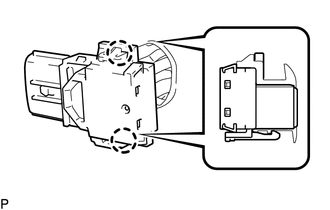
(a) Disengage the 2 claws to remove the No. 1 ultrasonic sensor. HINT: Use the same procedure for the RH side and LH side. |
 |
3. REMOVE NO. 2 ULTRASONIC SENSOR RETAINER
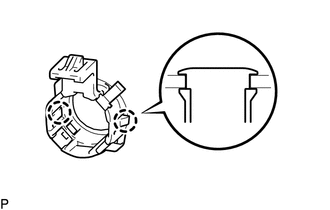
(a) Disengage the 2 claws to remove the No. 2 ultrasonic sensor retainer from the front bumper assembly. HINT: Use the same procedure for the RH side and LH side. |
 |
1. INSPECT NO. 1 ULTRASONIC SENSOR
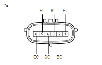
(a) Measure the resistance according to the value(s) in the table below. Standard Resistance:
If the result is not as specified, replace the No. 1 ultrasonic sensor. |
 |
1. INSTALL NO. 2 ULTRASONIC SENSOR RETAINER
(a) Engage the 2 claws to install the No. 2 ultrasonic sensor retainer to the front bumper assembly. Text in Illustration
NOTICE:
HINT:
|
 |
2. INSTALL NO. 1 ULTRASONIC SENSOR
(a) Engage the 2 claws to install the No. 1 ultrasonic sensor to the No. 2 ultrasonic sensor retainer.
NOTICE:
Push the No. 2 ultrasonic sensor retainer from the outside of the front bumper assembly when there is a gap between the No. 2 ultrasonic sensor retainer and the front bumper assembly surface. In this case, do not push on the No. 1ultrasonic sensor.
HINT:
Use the same procedure for the RH side and LH side.
3. INSTALL FRONT BUMPER ASSEMBLY
(See page  )
Test yourself
A quick Toyota Venza quiz: every answer comes with an explanation and a link to the manual page.