Audio / Video
Data Signal Circuit between Radio Receiver and Extension Module
DESCRIPTION
The stereo component tuner assembly sends the image data signal to the radio and display receiver assembly via this circuit.
WIRING DIAGRAM 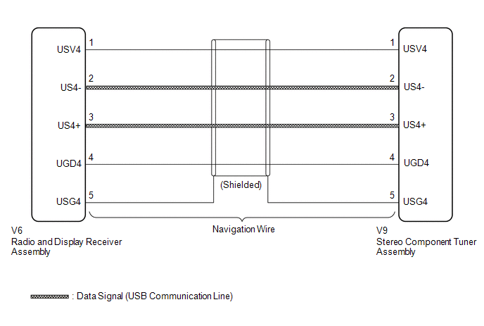 PROCEDURE
CHECK NAVIGATION WIRE
(a) Remove the navigation wire (See page  ).
(b) Measure the resistance according to the value(s) in the table below.
Standard Resistance:
Tester Connection | Condition | Specified Condition |
V9-1 (USV4) - V6-1 (USV4) |
Always |
Below 1 Ω |
V9-2 (US4-) - V6-2 (US4-) |
Always |
Below 1 Ω |
V9-3 (US4+) - V6-3 (US4+) |
Always |
Below 1 Ω |
V9-4 (UGD4) - V6-4 (UGD4) |
Always |
Below 1 Ω |
V9-5 (USG4) - V6-5 (USG4) |
Always |
Below 1 Ω |
V9-1 (USV4) - Body ground |
Always |
10 kΩ or higher |
V9-2 (US4-) - Body ground |
Always |
10 kΩ or higher |
V9-3 (US4+) - Body ground |
Always |
10 kΩ or higher |
V9-4 (UGD4) - Body ground |
Always |
10 kΩ or higher |
V9-5 (USG4) - Body ground |
Always |
10 kΩ or higher |
Text in Illustration
*a |
Front view of navigation wire connector
(to Radio and Display Receiver Assembly) |
*b |
Front view of navigation wire connector
(to Stereo Component Tuner Assembly) |
|
 |
| OK |
 |
PROCEED TO NEXT SUSPECTED AREA SHOWN IN PROBLEM SYMPTOMS TABLE |
| NG |
|
REPLACE NAVIGATION WIRE |
?
Test yourself
A quick Toyota Venza quiz: every answer comes with an explanation and a link to the manual page.
Was this page helpful?