Radio Receiver Power Source Circuit
This is the power source circuit to operate the radio and display receiver assembly.
WIRING DIAGRAM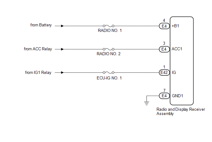
CAUTION / NOTICE / HINT
NOTICE:
Inspect the fuses for circuits related to this system before performing the following inspection procedure.
PROCEDURECHECK HARNESS AND CONNECTOR (RADIO AND DISPLAY RECEIVER ASSEMBLY POWER SOURCE)
(a) Disconnect the E4 and E42 radio and display receiver assembly connectors.
(b) Measure the resistance according to the value(s) in the table below.
Standard Resistance:
Tester Connection | Condition | Specified Condition |
|---|---|---|
E4-7 (GND1) - Body ground |
Always |
Below 1 Ω |
(c) Measure the voltage according to the value(s) in the table below.
Standard Voltage:
Tester Connection | Condition | Specified Condition |
|---|---|---|
E4-4 (+B1) - E4-7 (GND1) |
Always |
11 to 14 V |
E4-3 (ACC1) - E4-7 (GND1) |
Ignition switch ACC |
11 to 14 V |
E42-1 (IG) - E4-7 (GND1) |
Ignition switch ON |
11 to 14 V |
| OK |  | PROCEED TO NEXT SUSPECTED AREA SHOWN IN PROBLEM SYMPTOMS TABLE |
| NG | | REPAIR OR REPLACE HARNESS OR CONNECTOR |
Test yourself
A quick Toyota Venza quiz: every answer comes with an explanation and a link to the manual page.