Knock Sensor
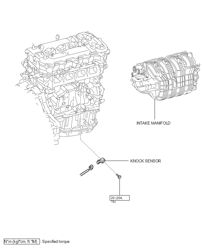
Removal REMOVAL PROCEDURE
1. REMOVE INTAKE MANIFOLD
(a) Remove the intake manifold (See page  ).
2. REMOVE KNOCK SENSOR
(a) Disconnect the sensor connector. |
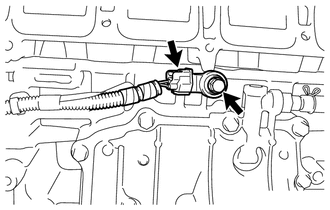 |
(b) Remove the bolt and sensor.
Inspection INSPECTION PROCEDURE1. INSPECT KNOCK SENSOR
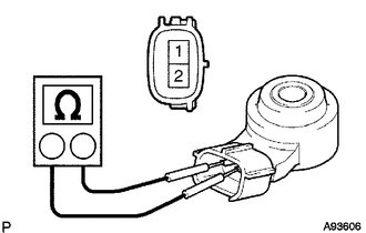
(a) Measure the resistance according to the value(s) in the table below. Standard Resistance:
If the result is not as specified, replace the knock sensor. |
 |
1. INSTALL KNOCK SENSOR
(a) Install the sensor with the bolt so that the sensor is angled as shown in the illustration. Torque: 20 N·m {204 kgf·cm, 15 ft·lbf} NOTICE: The acceptable installation angle of the sensor is between 7° upward and 10° downward from the horizontal position. HINT: Perform "Inspection After Repair" after replacing the knock control sensor (See page |
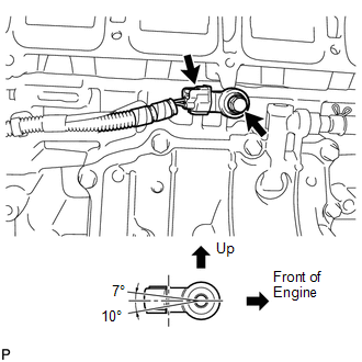 |
(b) Connect the sensor connector.
2. INSTALL INTAKE MANIFOLD
(a) Install the intake manifold (See page 
).
Test yourself
A quick Toyota Venza quiz: every answer comes with an explanation and a link to the manual page.