Installed parts
Assembly overview - installed parts
Assembly overview - installed parts

Note
The illustration shows the left side. The right side is handled in the same way.
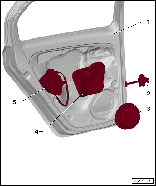
- Front door
- Remove and install
- adjust
- Door check strap
- Remove and install
- Speaker
- riveted into the door
- Cover
- Remove and install
- Door lock
- Remove and install
Assembly overview - adhesive pad

Note
The illustration shows the left side. The right side is handled in the same way.
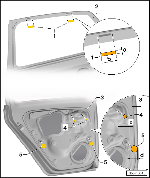
- Fabric tape
- 2 pieces per rear door
- If required, make from commercially available fabric adhesive tape.
- Dimensions: dimension -a- 15 mm, dimension -b- 60 mm
- Rear door
- Door frame, exterior
- Rear door
- Door interior
- Adhesive pad
- 2 pieces per rear door
- If required, make from commercially available fabric adhesive tape.
- Dimensions -d-: 19 mm Ø
- Adhesive pad
- 2 pieces per rear door
- If required, make from commercially available fabric adhesive tape.
- Dimensions -c-: front adhesive pad 30 mm Ø, rear adhesive pad 40 mm Ø
Assembly overview - door handle and door lock

Note
The illustration shows the left side. The right side is handled in the same way.
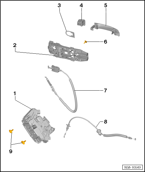
- Door lock
- Remove and install
- bearing bracket
- Remove and install
- Support
- Cover cap
- Remove and install
- Door handle
- Remove and install
- Bolt
- Tightening torque: 1.5 N·m
- Loosening this bolt releases the bearing bracket from the door.
- Cable
- from door lock -1- to bearing bracket -3-
- Cable
- from inside door release to door lock -1-
- with grommet for passage through the cover
- Bolt
- 2 pieces
- Tightening torque: 18 N·m
Removing and installing installed parts
Removing and installing door cover
Required Special Tools, Test and Measuring Equipment and Auxiliary Items
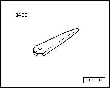
- Release Wedge -3409-

Note
Removing and installing applies only to the left cover. The right side is to be derived accordingly.
Removing

Carry out the following work:
- Remove the rear door trim → Body, assembly work, interior.
- If necessary, disconnect the connector on pressure sensor -4-.
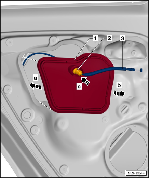
- Lift cover -1- off at the lower area -arrow a-.
- Pull cover -1- forward out of the door -arrows b-.

Note
If necessary for the following work, pull cable -3- with grommet -2- out of cover -1-. If fitted, disconnect the connector on the grommet.
Installing
Carry out the following work:
Replace a damaged seal with 1K adhesive sealant -D 469 101 A3-.
- Thread cable -3- with grommet -2- into cover -1-.
- Engage grommet -2- in cover -1-.
- Insert cover -1- into door -2- -arrows a-.
- Snap cover -1- into place all around -arrows b-.

Note
Check the cover by running your fingers around the edge.
Removing and installing door check strap
Required Special Tools, Test and Measuring Equipment and Auxiliary Items
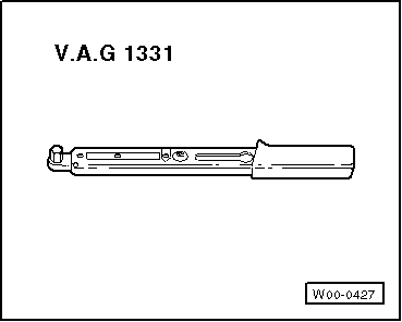
- Torque Wrench -V.A.G 1331-

Note
Removing and installing applies only to the left door check strap. The right side is to be derived accordingly.
Removing
Carry out the following work:
- Remove the rear door trim → Body, assembly work, interior.
- Remove self-adhesive cover, or remove front speaker → Communication.
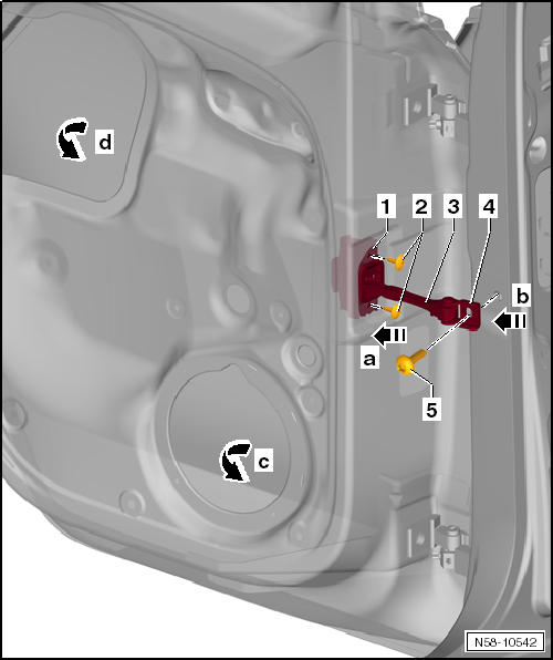
- Unscrew bolt -5- on the B-pillar.
- Unscrew bolts -2- and remove the door check strap -1-.
- On vehicles without a speaker, peel off the self-adhesive cover and remove the door check strap from the speaker opening -arrow c-.
- On vehicles with a speaker, remove the cover and take it out of this opening -arrow d-.
Installing
Carry out the following work:
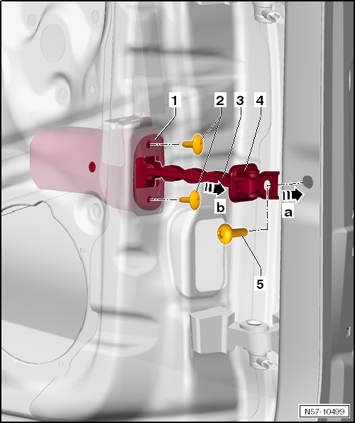
Installation is performed in the reverse order.
Tightening torque bolt -2-: 30 N·m.
Tightening torque, bolts -3-: 9 N·m.
Removing and Installing Striker
Required Special Tools, Test and Measuring Equipment and Auxiliary Items
- Torque Wrench -V.A.G 1331-
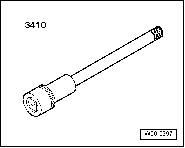
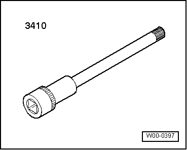
- Socket insert -3410-

Note
Removing and installing applies only to the left door striker. The right side is to be derived accordingly.

Removing
Carry out the following work:
- Unscrew bolts -2- and remove door striker -1-.
Installing
Carry out the following work:
- Position door striker -1- on B-pillar -3- and tighten bolts -2-.
Tightening torque bolts -2-: 20 N·m.
- Adjusting the door striker
Removing and installing door handle
Removing and installing door handle

Note
Removing and installing applies only to the left door handle. The right side is to be derived accordingly.
Removing
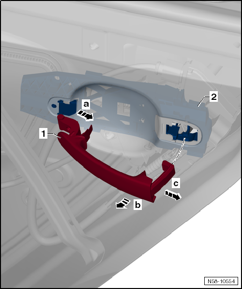
- Remove cover cap
- Pull door handle -1- slightly rearward -arrow a- out of the bearing bracket seat.
- Swivel door handle in direction of arrow b.
- Pull the door handle out of the bearing bracket -2- -arrow c-.
Installing
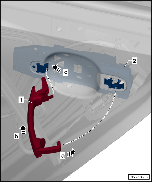
- Insert the door handle -1- into the bearing bracket at a right angle -arrow b-.
- Swing the door handle -1- into the door -arrow a-.
- Press door handle firmly forward -arrow c- into the seat in the bearing bracket.
Install cover cap.
- Afterwards, a function check must be performed with the door open.
Removing and installing cover cap (without lock cylinder)
Required Special Tools, Test and Measuring Equipment and Auxiliary Items
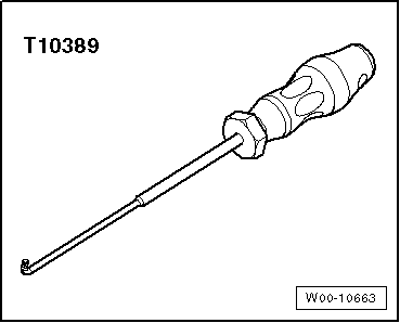
- Installation tool -T10389-
Removing
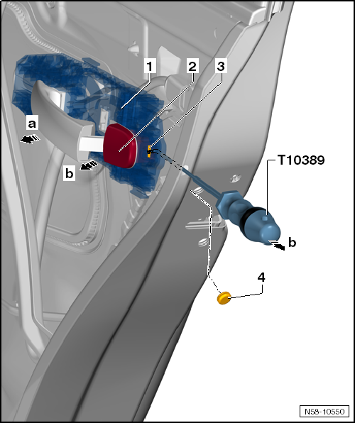
- Remove plug -4-.
- Guide installation tool -T10389- approx. 44 mm behind locking hook -3- of the bearing bracket.
- Pull installation tool -T10389- approx. 5 mm rearward -arrow-, until the hook unlocks.
- Pull door handle -1- off the door.
- Pull cover cap -1- out of the bearing bracket -arrow b-.
Installing
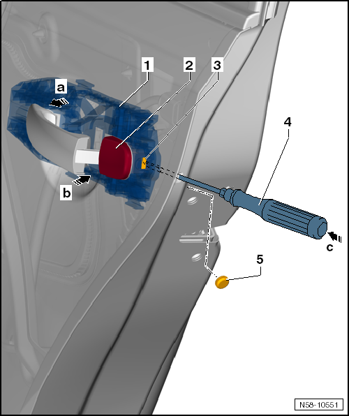
- Pull the door handle -1- off the door in the direction of arrow a.
- Slide cover cap -2- into the bearing bracket -arrow b-.
- Guide a flat-blade screwdriver -4- approx. 40 mm up to the locking hook -3- of the bearing bracket.
- Press cover cap -1- against the door.
- Press the screwdriver in approx. 5 mm -arrow c- until the hook locks.
- Attach plug -5-.
Removing and installing the bearing bracket
Required Special Tools, Test and Measuring Equipment and Auxiliary Items
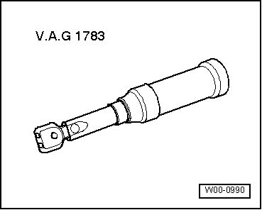
- Torque wrench -V.A.G 1783-

Note
Removal and installation is only described for the right bearing bracket. The left side is derived accordingly.
Removing
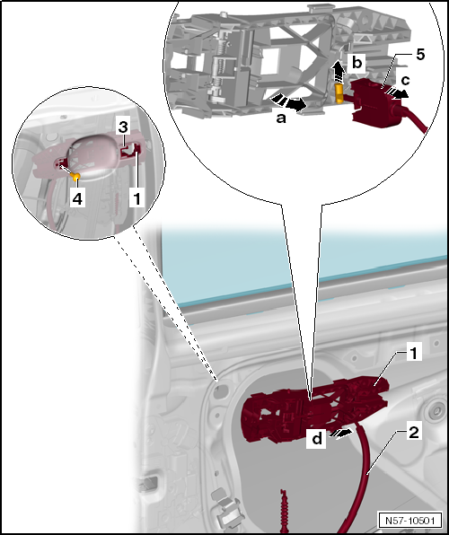
Carry out the following work:
- Remove the rear door trim → Body, assembly work, interior.
- Remove cover
- Remove cover cap
- Remove door handle
- Remove door lock
- Unscrew bolt -4- and remove washer -3-.
- Remove bearing bracket -1- from the front door -arrow d-.
Releasing the Bowden cable
- Unlock bracket -5- and swivel it out of the seat in the bearing bracket -arrow a-.
- Lift the Bowden cable pin out of the seat -arrow b-.
- Remove Bowden cable -2- from bearing bracket -1- -arrow c-.
Installing
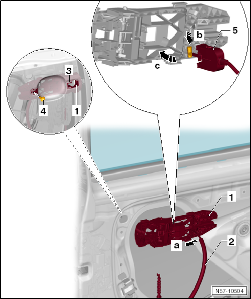
Carry out the following work:
Installation is carried out in the reverse order. Observe the following:
Tightening torque of bolt -4-: 1.5 N·m.
Removing and installing door lock
Required Special Tools, Test and Measuring Equipment and Auxiliary Items
- Torque Wrench -V.A.G 1331-

- Socket insert -3410-

Note
Removal and installation are described only for the right door lock. The left side is performed analogously.
Removing
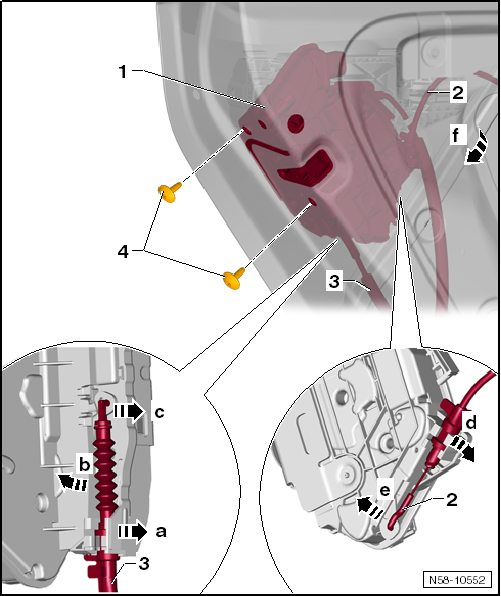
Carry out the following work:
- Remove the rear door trim → Body, assembly work, interior.
- Remove cover.
- Remove cover cap
- If fitted, disconnect plug connector.
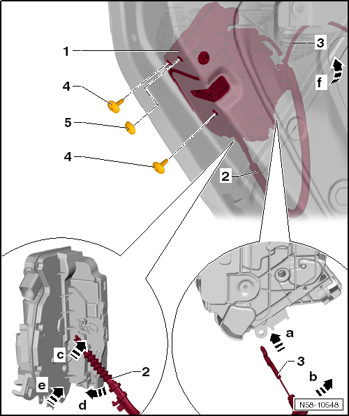
- Unscrew bolts -4-.
- Remove door lock -1- from the door -arrow f-.

Note
If required for the following work, the cables can be detached.
Detaching cable from bearing bracket
- Turn cable -3- 90° and remove from the holder -arrow a-.
- Swivel cable as far as necessary -arrow b- until it can be threaded out of the eyelet in door lock -1- -arrow c-.
Detaching cable to inside door release
- Turn cable -2- 90° and remove from the holder.
- Swivel cable as far as necessary -arrow d- until it can be threaded out of the eyelet in door lock -1- -arrow e-.
Installing
Carry out the following work:
- Install removed cables -2- and -3- on door lock -1-.
- Insert door lock -1- into the door -arrow f-.
- If fitted, connect plug connector.
- Screw in bolts -4-.
Tightening torque, bolts -4-: 18 N·m.
- Clip on cover cap -5-.
Installation is carried out in reverse order.
- Afterwards, be sure to perform a function check. If the cables are not correctly adjusted and locked, the door lock cannot be unlocked and the door therefore cannot be opened.
Removing and installing door seal
Removing and installing door inner seal
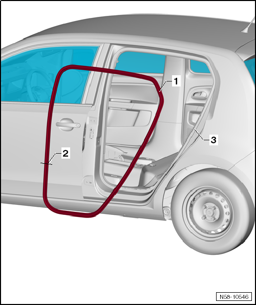
At the factory, the door inner seals are fitted with sealant, slipped onto the door flange and then rolled on.

Note
- When the seal is removed, the sealant is spread over the inside of the seal and the edges are slightly bent up. Once the seal is refitted, sealing and secure fit are no longer guaranteed.
- For this reason, every completely removed seal must be replaced with a so-called "hammer-on seal".
- On partially removed seals, press the edges of the seal together before installation.
- Removal and installation are described only for the left door inner seal. The right side is performed analogously.
- For better illustration, the rear door is removed.
Removing
Carry out the following work:
- Remove sill trim → Body assembly work interior.
- To remove the door inner seal, remove the necessary pillar trims → Body assembly work interior.
- Pull inner door seal -1- off body flange -3-.
Installing

Note
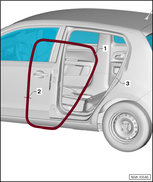
Do not kink vulcanized joint -2-.
Carry out the following work:
- Begin at the upper radius of the door opening by installing inner door seal -1-.
- Install pillar trims → Body assembly work interior.
- Install sill trim → Body assembly work interior.