Door
Assembly overview - Door
Assembly overview - Door hinges

Note
- The illustration shows the left side. The right side is handled in the same way.
- Always replace the door hinge bolts after loosening them.
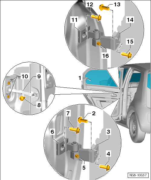
- Front door
- Remove and install
- adjust
- Bolt
- Always replace. Loosening once for door adjustment is permitted.
- Tightening torque: 50 N·m
- After replacing the B-pillar, a different tightening torque must be observed.
- Tightening torque after replacing the B-pillar: 20 N·m + 90º
- Door hinge
- Hinge is split.
- The lower part is connected to the upper hinge part by bolt -5-.
- Bolt
- Always replace. Loosening once for door adjustment is permitted.
- Tightening torque: 50 N·m
- installed from the vehicle interior
- To remove and install, the lower B-pillar trim must be removed.
- After replacing the B-pillar, a different tightening torque must be observed.
- Tightening torque after replacing the B-pillar: 20 N·m + 90º
- Bolt
- connects upper hinge part -3- with lower hinge part -6-
- Tightening torque: 23 N·m
- Door hinge
- The hinge is split.
- The upper part is connected to the lower hinge part by bolt -5-.
- Bolt
- Always replace. Loosening once for door adjustment is permitted.
- Tightening torque: 50 N·m
- Bolt
- Tightening torque: 30 N·m
- Door check strap
- Remove and install
- Bolt
- 2 pieces
- Tightening torque: 9 N·m
- Door hinge
- The hinge is split.
- The upper part is connected to the lower hinge part by bolt -16-.
- Bolt
- Always replace. Loosening once for door adjustment is permitted.
- Tightening torque: 50 N·m
- Bolt
- Always replace. Loosening once for door adjustment is permitted.
- Tightening torque: 50 N·m
- After replacing the B-pillar, a different tightening torque must be observed.
- Tightening torque after replacing the B-pillar: 20 N·m + 90º
- Door hinge
- Hinge is split.
- The lower part is connected to the upper hinge part by bolt -16-.
- Bolt
- Always replace. Loosening once for door adjustment is permitted.
- Tightening torque: 50 N·m
- installed from the vehicle interior
- To remove and install, the instrument panel must be removed.
- After replacing the B-pillar, a different tightening torque must be observed.
- Tightening torque after replacing the B-pillar: 20 N·m + 90º
- Bolt
- connects upper hinge part -3- with lower hinge part -6-
- Tightening torque: 23 N·m
Removing and installing the door
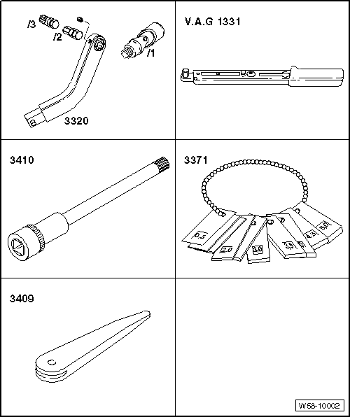
Required Special Tools, Test and Measuring Equipment and Auxiliary Items
- Key for door adjustment -3320-
- Joint for 3320 -3320/1-
- Bit insert for 3320 -3320/2-
- Bit insert for 3320 -3320/3-
- Torque Wrench -V.A.G 1331-
- Socket insert -3410-
- Adjustment gauge -3371-
- Release Wedge -3409-

Note
Removal and installation are described for the left front door only. Removal and installation of the right front door are carried out in the same way.
Removing
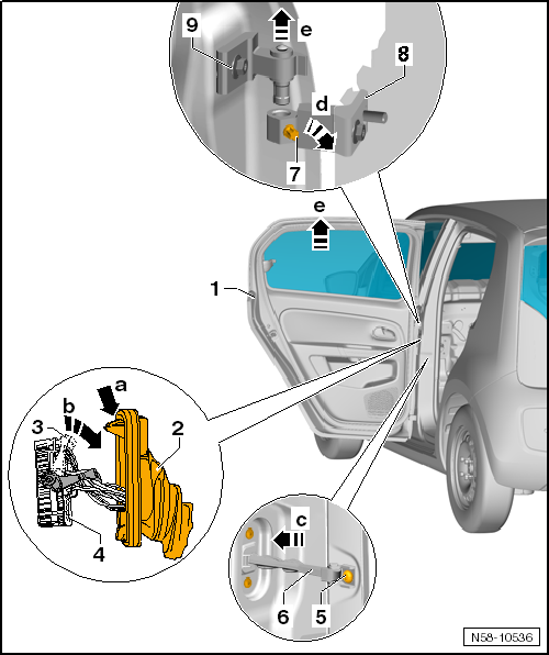
Carry out the following work:
- Unlock the bellows -2- by pressing the catch -arrow a- and pull it off the B-pillar.
- Swing locking lever -3- downward -arrow b- and disconnect electrical connector -4- from the coupling station.
- Loosen bolts -7- on the hinges.
- Unscrew bolt -5- for door check strap -6-.
- Push door check strap -6- inward -arrow c-.
- Lift front door -1- with hinges -9- upward -arrow e- off hinges -8-.
Installing
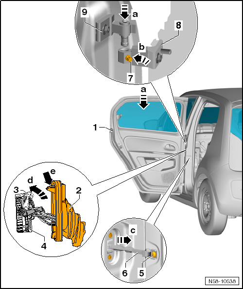
Carry out the following work:
Installation is carried out in the reverse order. Observe the following:

Caution!
Before hanging the rear door, the bearing of the door check strap must be folded inward toward the vehicle interior (to avoid paint damage).
Tightening torque for bolts -5-: 30 N·m.
Tightening torque for bolts -7-: 23 N·m.

Note
After hanging the front door, the hinge leaves must lie flush against each other.
- Adjust the rear door -1-.
- Observe gap dimensions of front door -1-.
Installing after replacing the B-pillar

Note
Installation after replacing the B-pillar is only described for the left front door. Installation after replacing the B-pillar for the right front door is derived accordingly.

WARNING!
If the B-pillar has been replaced, be sure to tighten the bolts on the B-pillar as follows.
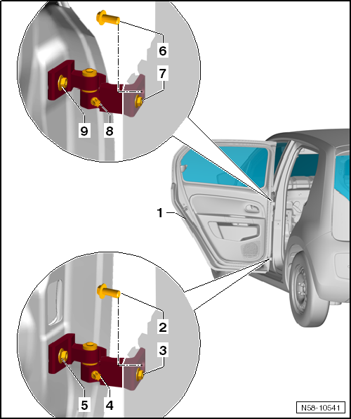
Carry out the following work:
- B-pillar has been replaced.
- Always replace the bolts. Loosening them once for door adjustment is permitted.
Installation is carried out in the reverse order. Observe the following:
- Install the rear door -1- and tighten bolts -2-, -3-, -6- and -7-. Tightening torque: 20 N·m + 90º.
Tightening torque for bolts -2-: 20 N·m + 90º.
Tightening torque, bolts -4-: 23 N·m.
- Adjust the rear door.
- Observe the gap dimensions of the rear door.
Adjusting the door
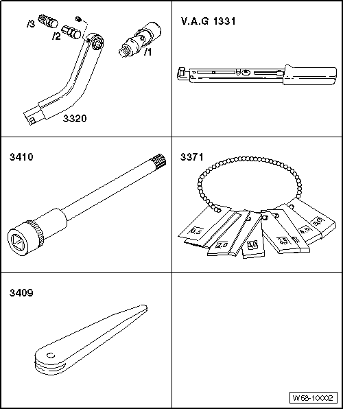
Required Special Tools, Test and Measuring Equipment and Auxiliary Items
- Key for door adjustment -3320-
- Joint for 3320 -3320/1-
- Bit insert for 3320 -3320/2-
- Bit insert for 3320 -3320/3-
- Torque Wrench -V.A.G 1331-
- Socket insert -3410-
- Adjustment gauge -3371-
- Release Wedge -3409-

Note
- Adjustment is only described for the left rear door. Adjustment of the right rear door is carried out accordingly.
- To adjust the front door, the vehicle must be standing on its wheels.
- The rear door is correctly adjusted when, in the closed position, the gap is even all around. It must not stand too far inward or outward, and the contours must be aligned.
- For checking the gap dimensions.
- After installation or adjustment work, apply corrosion protection to the hinges and bolts.
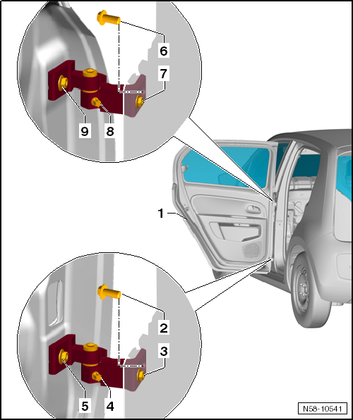
Carry out the following work:
Adjusting the gap dimensions
To set the gap dimensions correctly, bolts -2-, -3-, -6- and -7- on the B-pillar must be loosened.
- For bolts -3 and 7-, the lower B-pillar trim must be removed.
Adjusting the flush alignment
For correct adjustment of the flush alignment, loosen bolts -5- and -9-.
Use special tool door adjustment wrench -3320- with the corresponding bit insert for this.

Note
Other measures, such as straightening the rear door upward, are ineffective. If the door is then pressed down again, it will sag again.
Adjusting the striker.
Adjusting the striker
Required Special Tools, Test and Measuring Equipment and Auxiliary Items
- Torque Wrench -V.A.G 1331-
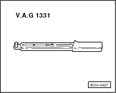
- Socket insert -3410-


Note
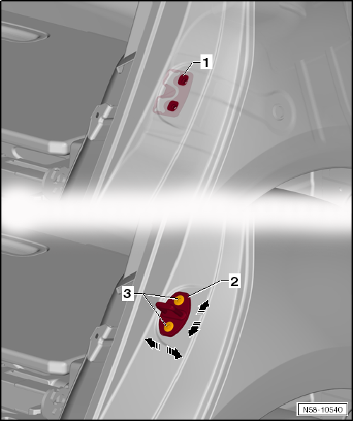
- The threaded plate -1- of the striker is attached to the pillar differently than previously known.
- The bracket outside the threaded plate is welded firmly to the pillar. The webs to the threaded plate are plastically deformable.
- To adjust striker -2- with bolts -3- loosened, considerable force must be applied.

Note
- Adjustment is only described for the left rear door. Adjustment of the right rear door is carried out accordingly.
- When closing, the rear door must latch fully without additional force and must have no play.
- The adjustment of the striker must not press the rear door upward or downward.
The striker is used to align the rear door with the side panel -arrows a- and -arrows b- (wind noise).
Carry out the following work:
- Loosen the striker -1- by loosening bolts -2- on the C-pillar.

Note
To adjust striker -1- with bolts -2- loosened, considerable force must be applied.
- Tighten bolts -2- of striker -1-.
Tightening torque bolts -2-: 20 N·m.