Control Units
Remove and install onboard supply control unit -J519-
General description:
The onboard supply control unit -J519- is attached to the rear of the relay carrier in the driver's footwell and performs the following functions in the vehicle:
- Fuel pump relay
- Electrical load management
- Driver door contact
- Sending dimming information on CAN
- Windshield wiper stages I, II and intermittent
- Reading in button of sensor unit for emergency braking function
- Hazard warning lights, turn signals, emergency brake warning flashing
- Horn
- Brake light
- Terminal 15 detection, S contact
- Rear window heater
- Tailgate release without central locking
- Terminal 30, interior light
- CAN bus drive
- CAN diagnostics
- CAN gateway
The following functions can be adapted:
- Adapt key with remote control
- Check key with remote control
- Deactivate factory mode

Note
- If the onboard supply control unit -J519- is to be replaced, the work procedure "Replacing onboard supply control unit" must be carried out in every case to read out the coding stored in the control unit.
- The following illustrations show removal on a left-hand drive vehicle. Removal and installation of the onboard supply control unit on a right-hand drive vehicle is performed accordingly, mirrored.
Removing

Note
If the onboard supply control unit is to be replaced, first carry out the work procedure "Replacing onboard supply control unit".
- Switch off the ignition and all electrical consumers and remove the ignition key.

Note
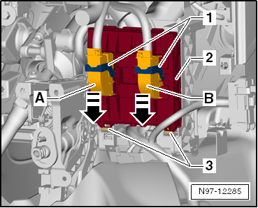
The following illustration shows the onboard supply control unit installed on the rear of the relay carrier.
- Swing the two brackets -1- of the primary lock down in the -arrow direction- and disconnect the two connectors -A- and -B- from the onboard supply control unit -J519--2-.
- Press the two locking buttons -3- and swing the onboard supply control unit -J519--2- out of the holder, starting from the bottom.
Installing
Installation is carried out in the reverse order, observing the following:
- Insert the onboard supply control unit -J519--2- into the receptacles -1- on the holder at the top first, then audibly clip it into the latches at the bottom -3-.
Replace onboard power supply control module
This program will assist you in replacing the onboard power supply control module. After replacement, the control module must be coded online, then factory mode must be deactivated and the data bus diagnostic interface -J533- must be coded again. The programs are entered in the test plan.
- Replace onboard power supply control module → Vehicle diagnostic tester.
Code onboard power supply control module
- Code onboard power supply control module → Vehicle diagnostic tester.
Adapt onboard power supply control module
The following components can be adapted with this function:
- Adapt key with remote control
- Check key with remote control
- Deactivate factory mode
Onboard power supply control module actuator diagnosis
This function test can be used to perform an actuator test on the following components:
- Lighting
- Windshield wiper and washer system
- Window, seat and mirror heating
- Central locking
- Warning, monitoring and sliding/tilting roof
- Windows
- Perform onboard power supply control module actuator diagnosis → Vehicle diagnostic tester.
Remove and install data bus diagnostic interface -J533-
The functions of the data bus diagnostic interface -J533- are integrated into the onboard power supply control module -J519-. The data bus diagnostic interface -J533- cannot be replaced separately.
- Remove and install onboard power supply control module -J519-.
Connectors
Repair electrical wiring harnesses and connectors
All instructions and notes for this chapter can be found under → Electrical system general information.
Vehicle diagnosis, measurement and information systems
All instructions and notes for this chapter can be found under → Electrical system general information.
Online system test
This test program performs the following steps:
- System test for the online connection
- Check of user authorization
- Test of correct line connection to the Volkswagen database
The prerequisite for this is the online connection (network connection) of the tester:
- Online system test → Vehicle diagnostic tester.