Front seats
Assembly overview - front seat

Note
The illustration shows the front seat, driver side. The front seat, passenger side is mirror-inverted accordingly.
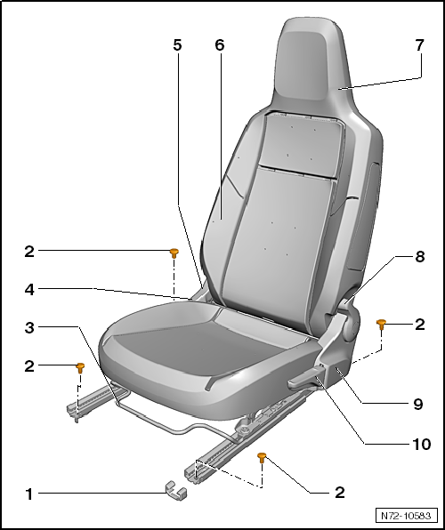
- Seat rail cover
- sill side
- Bolt
- 4 pieces
- 40 N·m
- Bracket
- for seat longitudinal adjustment
- Front seat trim
- tunnel side
- Remove and install
- Backrest adjustment lever
- tunnel side
- Remove and install
- Front backrest
- reclining angle adjustable
- Remove and install
- Head restraint
- integrated firmly in the seat
- Entry aid lever
- depending on equipment
- on vehicles without entry aid, a cover cap is fitted
- Remove and install
- Front seat trim
- sill side
- Remove and install
- Seat height adjustment lever
- sill side
- depending on equipment
- Remove and install
Assembly overview - front backrest

Note
The illustration shows the front backrest, driver side. The front backrest, passenger side is mirror-inverted accordingly.
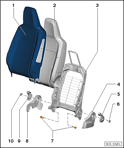
- Cover
- Remove and install
- Pad
- with or without backrest heating element (depending on equipment)
- Remove and install
- Backrest frame
- with integrated head restraint
- Remove and install
- Front seat trim
- sill side
- Remove and install
- Entry aid lever
- depending on equipment
- on vehicles without entry aid, a cover cap is fitted
- Remove and install
- Cover cap
- Bolt
- 4 pieces
- Self-locking
- Bolts are micro-encapsulated and must be replaced after every loosening
- Clean threaded holes for the bolts, e.g. with a thread tap
- 33 +- 3 N·m
- Front seat trim
- tunnel side
- Remove and install
- Backrest adjustment lever
- Remove and install
- Cover cap
Assembly overview - seat pan

Note
The illustration shows the seat pan, driver side. The seat pan, passenger side is mirror-inverted accordingly.
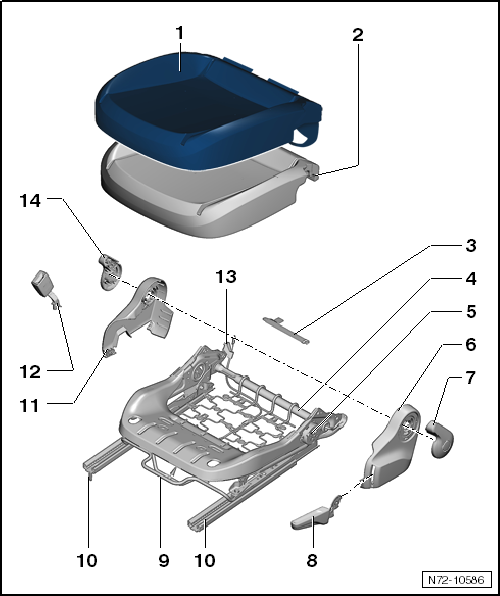
- Cover
- Remove and install
- Pad
- with or without heating element
- Remove and install
- Passenger seat occupancy sensor -G128-
- Remove and install
- Seat pan
- Seat height adjustment
- depending on equipment
- Remove and install
- Front seat trim
- sill side
- Remove and install
- Entry aid lever
- depending on equipment
- on vehicles without entry aid, a cover cap is fitted
- Remove and install
- Seat height adjustment lever
- sill side
- depending on equipment
- Remove and install
- Bracket
- for seat longitudinal adjustment
- Seat rails
- Front seat trim
- tunnel side
- Remove and install
- Front seat belt buckle
- Remove and install
- Entry aid
- depending on equipment
- Backrest adjustment lever
- Remove and install
Removing and installing front seat
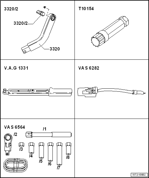
Required Special Tools, Test and Measuring Equipment and Auxiliary Items
- Key for door adjustment -3320-
- Socket insert XZN 10 -T10154-
- Torque Wrench -V.A.G 1331-
- Airbag adapter -VAS 6282-
- Brake bleeding tool set -VAS 6564-

Note
Removal and installation are described for the driver's front seat. Removal and installation of the front passenger seat are mirror-image and follow the same procedure.
Removing

WARNING!
Observe the safety precautions when working on the airbag.
- On e-up! vehicles, disconnect service plug for high-voltage system -TW-.
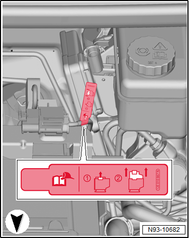
- Disconnect vehicle battery → Electrical system.
- Move the front seat to the frontmost position with the fore/aft adjustment.
Vehicles with seat height adjustment
- Move the front seat to the highest position with the seat height adjustment.
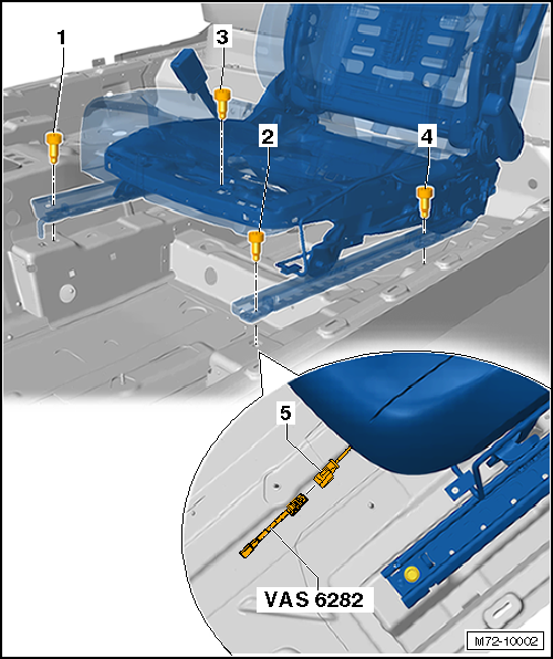
- Unscrew bolts -3- and -4-.
Vehicles without height adjustment
- Unscrew bolt -3-.
- Unscrew bolt -4- using the door adjustment key -3320- and the brake bleeding tool set -VAS 6564/1-.
Continuation for all vehicles
- Move the front seat to the rearmost position with the fore/aft adjustment.

WARNING!
Electrostatic discharge can cause the airbag to deploy unintentionally. Therefore, the technician must discharge static electricity before disconnecting the electrical connector. This can be done, for example, by briefly touching the body or the door striker.
- Depending on vehicle equipment, disconnect any existing electrical connectors from the front seat.
- Connect airbag adapter -VAS 6282-.
- Unscrew bolts -1- and -2-.

Caution!
To avoid damage, do not lift or transport the seat by attachments such as the seat belt buckle, the fore/aft adjustment bracket, the seat height adjustment lever, or the seat trim.
- Grip between the front backrest and the seat pan with the right hand. Grip the front end of the seat pan with the left hand and remove the front seat from the vehicle.
Installing
- Place the front seat into the vehicle through the front door.
- Lift the front seat over the centering pins on the tunnel side into the corresponding openings in the floor.

WARNING!
If the thread in the seat cross member mounting bracket is damaged during seat installation, reworking the damaged thread is not permitted. In this case, the seat cross member mounting bracket must be replaced.
If the thread in the seat cross member mounting bracket is damaged:
- Replace the affected seat cross member mounting bracket.
- Tighten bolt -1-.
- Tighten bolt -2-.
- Disconnect airbag adapter -VAS 6282-.
- Lock the wiring harness of the side airbag -5- into the connector station.
- Depending on vehicle equipment, lock the remaining electrical connectors on the front seat.

WARNING!
Make sure no persons are in the vehicle.
- Move the seat to the frontmost position with the fore/aft adjustment.
- Tighten bolt -3-.
- Tighten bolt -4-.
- On e-up! vehicles, connect the service plug for high-voltage system -TW-.
- Connect vehicle battery → Electrical System.
Connecting and disconnecting airbag adapter
Required Special Tools, Test and Measuring Equipment and Auxiliary Items
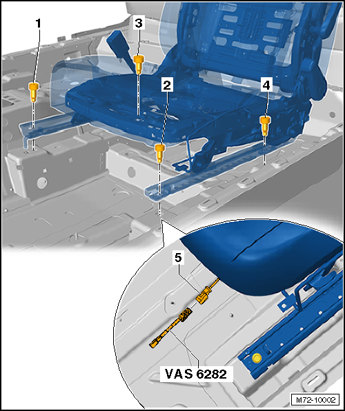
- Airbag adapter -VAS 6282-

Note
Connecting and disconnecting are described for the driver's front seat. Connecting and disconnecting for the front passenger seat are mirror-image and follow the same procedure.
Connecting

WARNING!
Observe the general safety regulations when working on airbag, belt tensioner, and battery disconnect units (pyrotechnic components).

- On e-up! vehicles, disconnect service plug for high-voltage system -TW-.
- Disconnect vehicle battery → Electrical system.
- Move the front seat to the rearmost and highest position with the fore/aft adjustment and seat height adjustment.
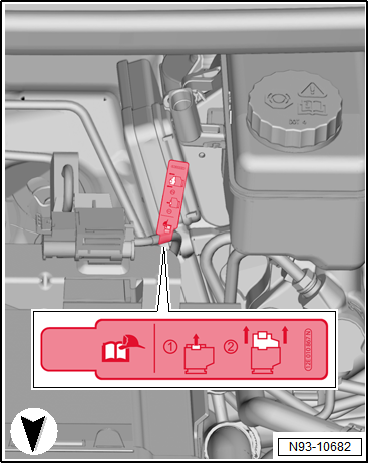

WARNING!
Electrostatic discharge can cause the airbag to deploy unintentionally. Therefore, the technician must discharge static electricity before disconnecting the igniter and ground wires. This can be done, for example, by briefly touching the body or the door striker.
- Disconnect the electrical connector for the side airbag under the front seat.
- Connect airbag adapter -VAS 6282- to the wiring harness of the side airbag -5-.

Caution!
The airbag adapter -VAS 6282- must remain connected to the seat until the seat has been reinstalled.

Disconnecting
- Disconnect in reverse order.
Removing and installing entry aid actuating lever
Required Special Tools, Test and Measuring Equipment and Auxiliary Items
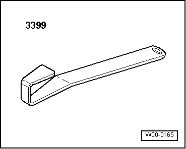
- Installation tool -3399-

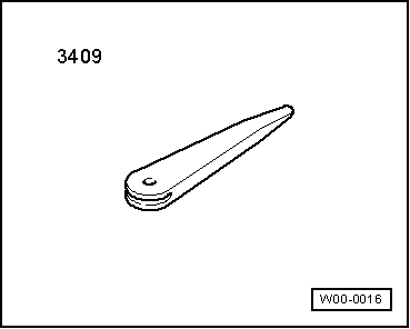
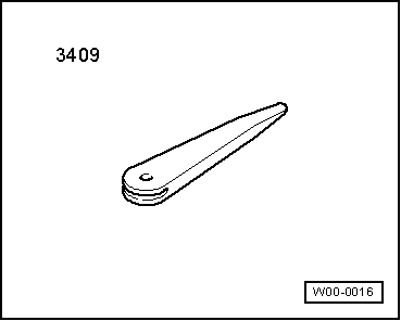
- Release Wedge -3409-

Note
Removal and installation are described for the left front seat. Removal and installation of the right front seat follow the same procedure, mirror-image.
Removing
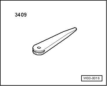
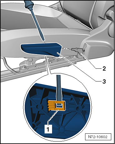
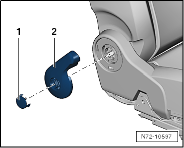
- Remove cover cap -1- using removal wedge -3409-.

Note
Alternatively, the cover cap can be carefully removed with a screwdriver.
- Carefully pull the entry aid actuating lever -2- off the shaft.

Note
The entry aid actuating lever can also be removed using installation tool -3399-.
Installing

Note
Before installation, check all fasteners for damage and replace them if necessary.
- Installation is performed in the reverse order.

Removing and installing seat height adjustment actuating lever
Removing
- Pull seat height adjustment actuating lever -3- upward and release the tab of the handle -1- with a screwdriver.
- Pull seat height adjustment actuating lever -3- off the seat height adjustment -2-.
Installing

Note
Before installation, check all fasteners for damage and replace them if necessary.
- Installation is performed in the reverse order.
Removing and installing backrest adjustment actuating lever
Required Special Tools, Test and Measuring Equipment and Auxiliary Items
- Installation tool -3399-
- Release Wedge -3409-

Note
Removal and installation are described for the left front seat. Removal and installation of the right front seat follow the same procedure, mirror-image.
Removing

- Remove cover cap -1- using removal wedge -3409-.

Note
Alternatively, the cover cap can be carefully removed with a screwdriver.
- Carefully pull backrest adjustment actuating lever -2- off the shaft.

Note
The backrest adjustment actuating lever can also be removed using installation tool -3399-.
Installing

Note
Before installation, check all fasteners for damage and replace them if necessary.
- Installation is performed in the reverse order.
Removing and installing front seat trim
Removing and installing front seat trim, front seat without height adjustment
Required Special Tools, Test and Measuring Equipment and Auxiliary Items
- Release Wedge -3409-
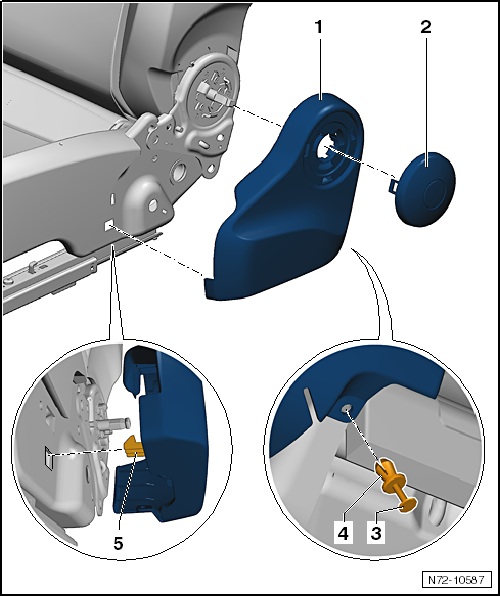
Removing on sill side
- Move the front seat to the frontmost position with the fore/aft adjustment.
Front seat without entry aid
- Remove cover cap -2- from front seat trim -1- using removal wedge -3409-.
Front seat with entry aid
- Remove entry aid actuating lever.

Note
- The entry aid actuating lever is not shown in the illustration.
- The entry aid actuating lever replaces cover cap -2-.
Continuation for all front seats
- Remove expansion pin -3- and take expanding clip -4- out of front seat trim -1-.
- Release locking lug -5- on the seat frame using removal wedge -3409-.
- Remove front seat trim -1-.
Installing

Note
Before installation, check all fasteners for damage and replace them if necessary.
- Installation is performed in the reverse order.
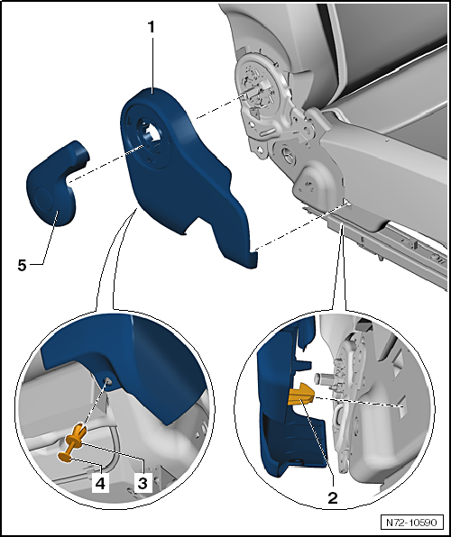
Removing on tunnel side
- Remove backrest adjustment actuating lever -5-.
- Remove expansion pin -4- and take expanding clip -3- out of front seat trim -1-.
- Release locking lug -2- on the seat frame using removal wedge -3409-.
- Remove front seat trim -1-.
Installing

Note
Before installation, check all fasteners for damage and replace them if necessary.
- Installation is performed in the reverse order.
Removing and installing front seat trim, front seat with height adjustment
Required Special Tools, Test and Measuring Equipment and Auxiliary Items
- Release Wedge -3409-
Removing on sill side
- Move the front seat to the frontmost position with the fore/aft adjustment.
Front seat without entry aid
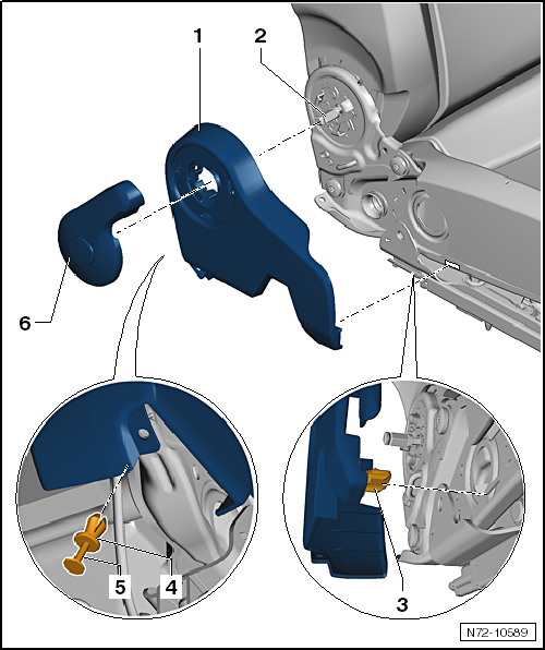
- Remove cover cap -2- from front seat trim -1- using removal wedge -3409-.
Front seat with entry aid
- Remove entry aid actuating lever.

Note
- The entry aid actuating lever is not shown in the illustration.
- The entry aid actuating lever replaces cover cap -2-.
Continuation for all front seats
- Remove seat height adjustment actuating lever.
- Remove expansion pin -3- and take expanding clip -4- out of front seat trim -1-.
- Pull front seat trim -1- over shaft -6-.
- Slide front seat trim -1- out of the receptacle on the seat frame in the direction of travel -arrow-.

Installing

Note
Before installation, check all fasteners for damage and replace them if necessary.
- Installation is performed in the reverse order.
Removing on tunnel side
- Remove backrest adjustment actuating lever -6-.
- Expansion pin -5- remove and expansion clip -4- from front seat trim -1- take out.
- Pull front seat trim -1- over shaft -2-.
- Push front seat trim -1- out of receptacle -3- of seat frame in direction of travel.
Installing

Note
Before installation, check all fasteners for damage and replace them if necessary.
- Installation is performed in the reverse order.
Removing and installing seat height adjuster
Required Special Tools, Test and Measuring Equipment and Auxiliary Items
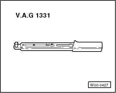
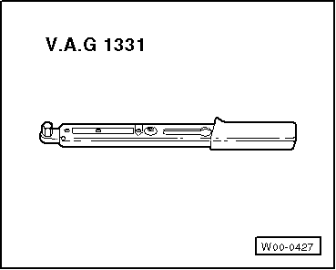
- Torque Wrench -V.A.G 1331-
Removing
- Move front seat to front, highest position, then lower it by one stroke.
- Remove front seat trim on sill side.
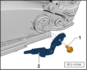
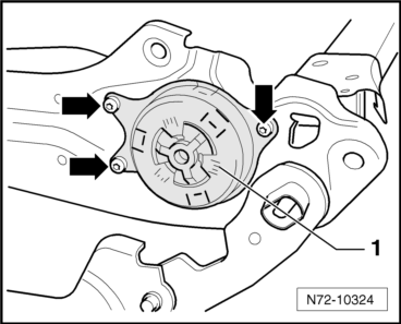
- Unscrew bolt -1- (20 N·m) and remove operating lever -2-.
- Unscrew bolts -arrows- (10 N·m).
- Loosen seat height adjuster -1- and remove.
Installing
Installation is carried out in the reverse order of removal, observing the following:
- When installing the seat height adjuster, a second technician must press the front seat slightly downward via the seat backrest.
Removing and installing front backrest
Removing and installing front backrest, front backrest without entry aid

Note
Removal and installation are described for the left front seat. Removal and installation of the right front seat follow the same procedure, mirror-image.
Required Special Tools, Test and Measuring Equipment and Auxiliary Items
- Torque Wrench -V.A.G 1331-
Removing
- Remove front seat.
- Remove trim on front seat.
- Expose all electrical wiring harnesses and disconnect electrical connectors.
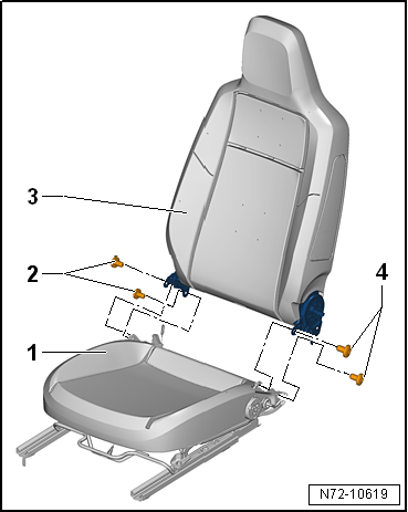
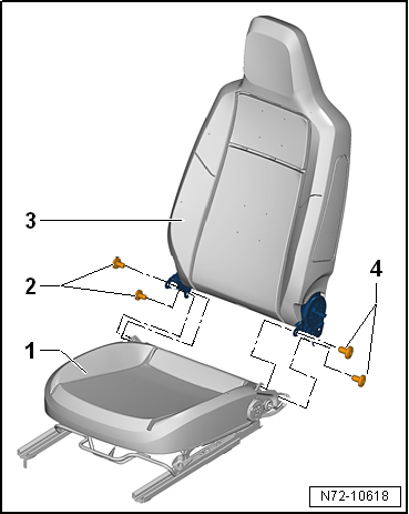
- Unscrew bolts -2- and -4-.

Note
- Bolts are micro-encapsulated and must be replaced after each removal.
- Before installing the new bolts, clean the threaded holes for the bolts, e.g. with a thread tap.
- Remove backrest -3- from seat pan -1-.
Installing
- Installation is performed in the reverse order.
Removing and installing front backrest, front backrest with entry aid

Note
Removal and installation are described for the left front seat. Removal and installation of the right front seat follow the same procedure, mirror-image.
Required Special Tools, Test and Measuring Equipment and Auxiliary Items
- Torque Wrench -V.A.G 1331-

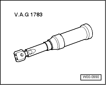
- Torque wrench -V.A.G 1783-
Removing
- Remove front seat.
- Remove trim on front seat.
- Unscrew bolt -1- of entry aid (1.5 N·m).
- Release entry aid -2- from seat backrest frame and remove.
- Expose all electrical wiring harnesses and disconnect electrical connectors.
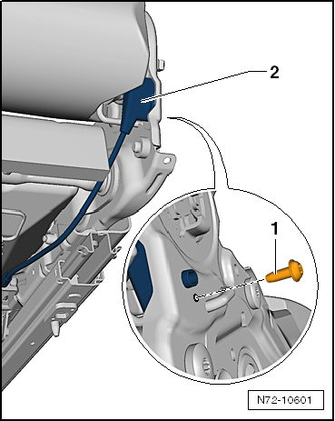
- Unscrew bolts -2- and -4-.

Note
- Bolts are micro-encapsulated and must be replaced after each removal.
- Before installing the new bolts, clean the threaded holes for the bolts, e.g. with a thread tap.
- Remove backrest -3- from seat pan -1-.
Installing
- Installation is performed in the reverse order.