Ignition system, glow plug system
Ignition system
Assembly overview - Ignition system
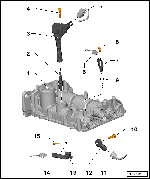
- Cylinder head cover
- Spark plug
- removing and installing with spark plug wrench -3122 B-
- Type and electrode gap "Test data, spark plugs"
- 25 N·m
- Ignition coil 1 with output stage -N70-
- Ignition coil 2 with output stage -N127-
- Ignition coil 3 with output stage -N291-
- Removing and Installing "Ignition Coils with Output Stages"
- Bolt
- 8 N·m
- Connector
- black
- 4-pin
- Bolt
- for Hall sender -G40-
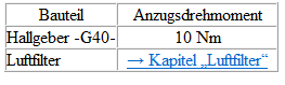
- 10 N·m
- Hall sender -G40-
- Removing and Installing "Hall Sensor -G40-"
- Connector
- black
- 3-pin
- for Hall sender -G40-
- Sealing ring
- Replace if damaged
- Bolt
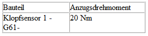
- Tightening torque affects knock sensor function
- 20 N·m
- Connector
- black
- 2-pin
- for knock sensor 1 -G61-
- Connector contacts gold-plated
- Knock sensor 1 -G61-
- Removing and Installing "Knock Sensor 1 -G61-"
- Connector contacts gold-plated
- Engine speed sensor -G28-
- Removing and Installing "Engine Speed Sensor -G28-"
- Connector
- black
- 3-pin
- for engine speed sensor -G28-
- Bolt
- for engine speed sensor -G28-
- 8 N·m
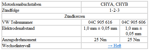
Specifications, spark plugs
Removing and installing ignition coils with power output stages

Required Special Tools, Test and Measuring Equipment and Auxiliary Items
- Torque wrench -VAS 6854-
- Puller -T10530-

Note
- The ignition coils are easier to pull out when the engine is warm.
- The grease used during initial installation of the ignition coils makes it easier to release the spark plug connectors when the engine is warm.
- Ignition coils with power output stage and spark plug connectors are available individually for repairs → Electronic Parts Catalog (ETKA).
Removing
- Disconnect hose -1- from air filter housing.
- Pull air filter housing upward off the bolts at points -2- and -3-.
- Push the air filter housing with the intake connector out of mount -4- in the -arrow direction-.
- Remove the air filter housing from the engine compartment.

- Unlock connector -1- and disconnect it.
- Unscrew bolts -2-.

- Press puller -T10530- all the way into the bore of ignition coil -1-.
- Tighten knurled nut -2- in direction of -arrow-.

- Pull ignition coil off puller -T10530- out of cylinder head cover in direction of -arrow-.
Installing
Installation is carried out in the reverse order. Observe the following:
- Insert all ignition coils loosely into spark plug wells.
- Align ignition coils with connectors and push all connectors onto ignition coils at the same time.
- Press ignition coils evenly onto spark plugs by hand (do not use an impact tool).
- Tighten mounting bolt to specified torque using torque wrench -VAS 6854-.

Tightening torques

Removing and installing knock sensor 1 -G61-
Required Special Tools, Test and Measuring Equipment and Auxiliary Items
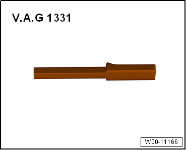
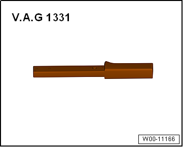
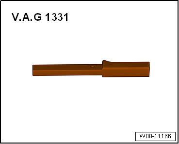
- Torque Wrench -V.A.G 1331-
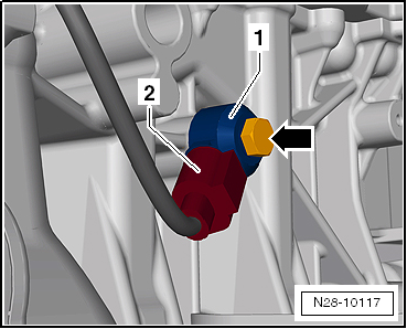
Removing
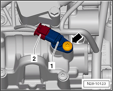
- Unlock and disconnect connector -2-.
- Unscrew bolt -arrow- and remove knock sensor 1 -G61--1- from engine.
Installing
Installation is carried out in the reverse order. Observe the following:
Tightening torque affects function of knock sensor 1 -G61-.
Tightening torques
Removing and installing Hall sensor -G40-
Required Special Tools, Test and Measuring Equipment and Auxiliary Items
- Torque Wrench -V.A.G 1331-
Removing
Installation location.
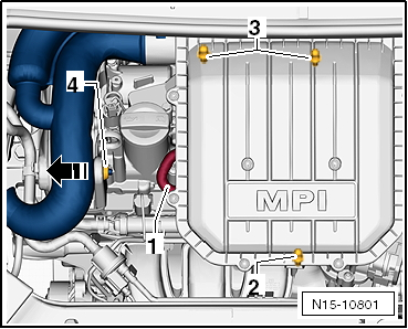
- Disconnect hose -1- from air filter housing.
- Pull air filter housing upward off the bolts at points -2- and -3-.
- Push the air filter housing with the intake connector out of mount -4- in the -arrow direction-.
- Remove the air filter housing from the engine compartment.
- Unlock and disconnect connector -2-.
- Unscrew bolt -arrow-.
- Remove Hall sensor -G40--1-.
Installing
Installation is carried out in the reverse order. Observe the following:
Replace sealing ring if damaged.
Tightening torques
Removing and installing engine speed sensor -G28-
Required Special Tools, Test and Measuring Equipment and Auxiliary Items
- Torque Wrench -V.A.G 1331-
- Tension strap -T10038-

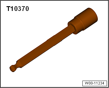
- Socket insert SW 4 -T10370-
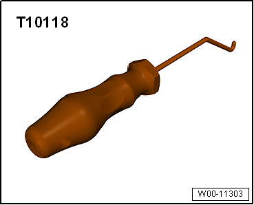
- Assembly tool -T10118-
Removing
Installation location.
- Remove fastening bolts -arrows- of the torque strut.
- Bolted connection -1- must not be loosened.

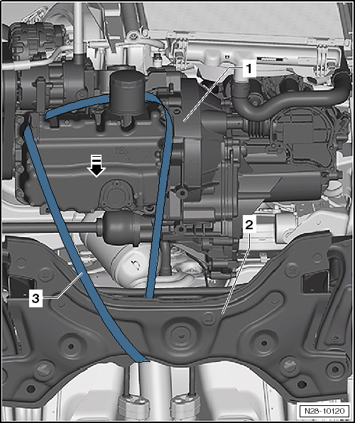
- Attach tension strap -T10038--3- to engine -1- and engine carrier -2- as shown.
- Pull engine -1- in direction of -arrow- using tension strap -T10038-.
- Make sure all components have sufficient clearance.
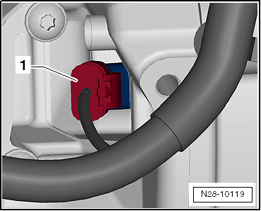
- Unlock connector -1- and disconnect it.
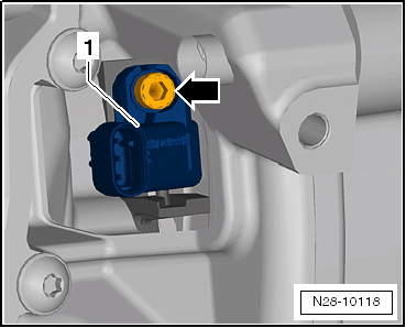
- Unscrew bolt -arrow- using socket insert SW 4 -T10370-.
- Remove engine speed sensor -G28--1-.
Installing
Installation is carried out in the reverse order. Observe the following:
Secure bolt -arrow- against falling.
Tightening torques
